
Index 275
Electric iron thermostat circuit
Published:2011/5/4 19:26:00 Author:Christina | Keyword: Electric iron, thermostat
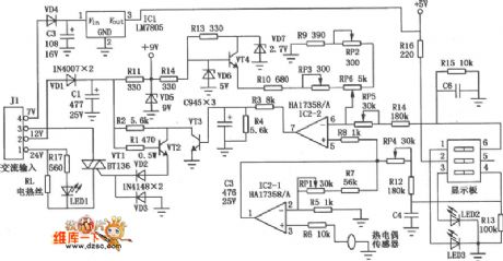
The Electric iron thermostat circuit is as shown:
(View)
View full Circuit Diagram | Comments | Reading(4374)
Auto wiper speed control circuit
Published:2011/5/4 19:34:00 Author:Christina | Keyword: Auto, wiper, speed control
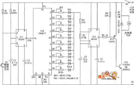
The auto wiper speed control circuit is as shown in figure. It controls the speed of wiper between the one to ten times per second, this device is flexible and can save power.
(View)
View full Circuit Diagram | Comments | Reading(1392)
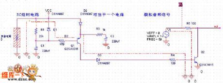
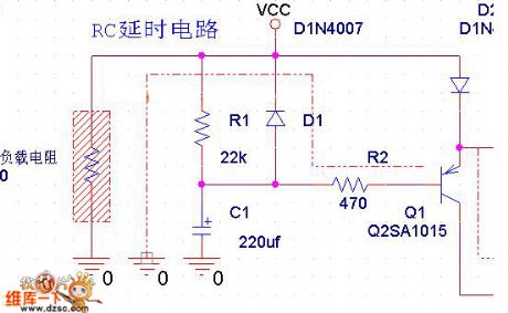
delay shutdown discharge circuit diagram
Published:2011/5/4 9:40:00 Author: | Keyword: delay, shutdown, discharge
View full Circuit Diagram | Comments | Reading(548)
regulator circuit diagram
Published:2011/5/4 9:17:00 Author: | Keyword: regulator, circuit
View full Circuit Diagram | Comments | Reading(540)
analyzing shutdown quiet current circuit diagram
Published:2011/5/4 9:43:00 Author: | Keyword: shutdown, quiet, current
View full Circuit Diagram | Comments | Reading(507)
analyzing shutdown quiet diagram
Published:2011/5/4 9:43:00 Author: | Keyword: shutdown, quietly
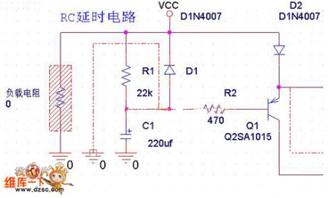
diagram:Now ,analyze shutdown quiet diagram
(View)
View full Circuit Diagram | Comments | Reading(475)
Gaoshi AV9092B amplifier display and control circuit diagram(-)
Published:2011/5/4 9:05:00 Author:Nancy | Keyword: Gaoshi, amplifier, display and control
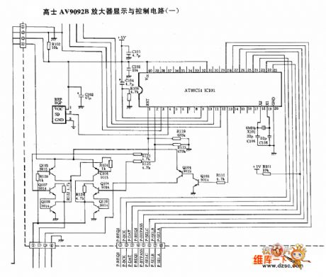
(View)
View full Circuit Diagram | Comments | Reading(452)
Automatic emergency light circuit
Published:2011/5/4 4:44:00 Author:Christina | Keyword: Automatic, emergency light
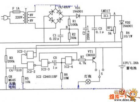
Figure: Automatic emergency light circuit (View)
View full Circuit Diagram | Comments | Reading(1634)
Using NE555 Skillfully as Holiday Lights Controller Circuit
Published:2011/5/4 8:05:00 Author:Joyce | Keyword: Using NE555 Skillfully as, Holiday Lights, Controller, NE555
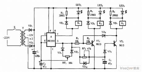
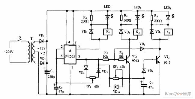 Using NE555 Skillfully as Holiday Lights Controller Circuit (View)
View full Circuit Diagram | Comments | Reading(528)
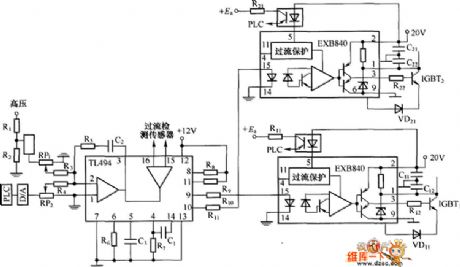
KA3842 switch power supply control integrated circuit diagram
Published:2011/5/4 2:55:00 Author:Nicole | Keyword: switch, power supply control
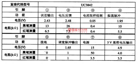
KA3842 is a switch power supply control integrated circuit which is produced by South Korea's Samsung, it is widely used in color TVs, color displays, air conditioners and other kinds of electric appliance switch power supply.
1, functional characteristics
KA3842 integrated circuit contains oscillation circuit, width regulation pulse control circuit, reference voltage circuit, error signal process circuit, current sampling protection circuit, under-voltage overvoltage protection circuit and other adjuvant functional circuit.
2, pin function and data
KA3842 integrated circuit adopts 8-foot dual in-line package, the integrated circuit's pin function and data are as shown in chart 1-1.
(View)
View full Circuit Diagram | Comments | Reading(2088)
TC9316F-15 movement logic control integrated circuit diagram
Published:2011/5/4 3:36:00 Author:Ecco | Keyword: movement , logic control, integrated circuit
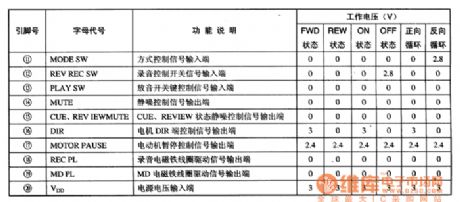
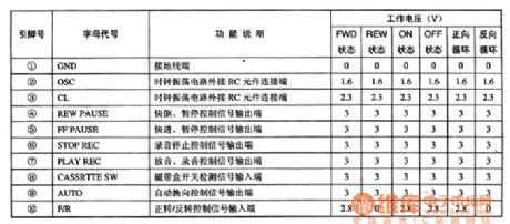
TC9316F-015 is a movement logic control integrated circuit produced by Toshiba, it is widely used in Epworth, Toshiba, Sanyo and domestic players, video machines. TC9316F-015 uses 20 feet package in double row, the pin functions and data are listed in Table 1. Table 1 shows TC9316F-015 pin functions and data.
(View)
View full Circuit Diagram | Comments | Reading(535)
Singlechip storage battery monitor circuit based on PIC12C508
Published:2011/5/3 3:51:00 Author:May | Keyword: singlechip, battery monitor
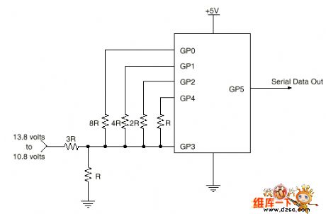
Brief Introduction
Normally, its rating value is 12V in 12V lead acid storage battery of trucks, cars, entertainment cars and uninterruptible power supply. This circuit monitors battery, charging and discharging curve, and it gives present voltage value and predicts the leavings time to supply end.
The voltage is 13.8V when 12V battery is fully charged, and it is 10.8V when 12V battery is fully released. It is linear in 3V range. It can use to predict the time value UPS
The diagram explains one bit A/D converter. It storages high, low and open three states in the resistor of single chip’s GP0, GP1, GP2, and GP4 pins. It allows GP3 input end as voltage comparator.
The circuit diagram:
(View)
View full Circuit Diagram | Comments | Reading(1343)
Accord sedan automatic temperature control system circuit diagram
Published:2011/5/4 2:08:00 Author:Rebekka | Keyword: Accord sedan, temperature control system
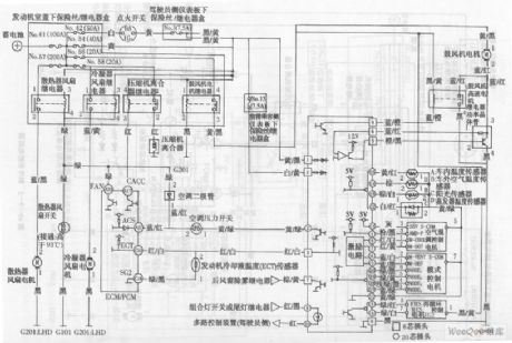
Accord sedan automatic temperature control system circuit diagram. (View)
View full Circuit Diagram | Comments | Reading(1094)
Photocoupler AC switches circuit diagram
Published:2011/5/4 2:01:00 Author:Rebekka | Keyword: Photocoupler AC switches
Photocoupler AC switches circuit diagram. (View)
View full Circuit Diagram | Comments | Reading(675)
Dynamic fit light control AC switches circuit diagram
Published:2011/5/4 1:59:00 Author:Rebekka | Keyword: Dynamic fit light control, AC switches

Dynamic fit light control AC switches circuit diagram. (View)
View full Circuit Diagram | Comments | Reading(800)
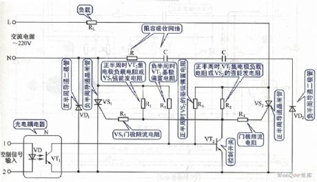
Both-way thyristor motor control circuit diagram 1
Published:2011/5/4 1:42:00 Author:Rebekka | Keyword: Both-way thyristor motor control
Both-way thyristor motor control circuit diagram. (View)
View full Circuit Diagram | Comments | Reading(760)
Both-way thyristor motor control circuit diagram 2
Published:2011/5/4 1:48:00 Author:Rebekka | Keyword: Both-way thyristor motor control
Both-way thyristor motor control circuit diagram.
(View)
View full Circuit Diagram | Comments | Reading(1419)
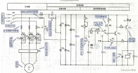
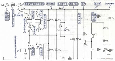
Secure electronic firecracker circuit
Published:2011/5/3 8:25:00 Author:Christina | Keyword: Secure, electronic firecracker

The Secure electronic firecracker circuit is as shown in the figure. ICl is the KD-5601 integrated circuit which can issues the sound of firecracker. When you using the match to fire the electronic firecracker, the match's light acts on the photoresistor RG to let the resistance decreases rapidly, the transistor VTl gets into the conduction state, ICl starts to work because the positive pulse. The output signal of ICl is magnified by the composite pipe which is composed of the transistor VT2, VT3, and it promotes the loud speaker BL to send out the sound of firecracker. At the same time, three different colors of light-emitting diode LEDl ~ LED3 turn on too, and the light spreads to the top of the glass tube by the optical fiber. After a few seconds, the circuit automatically stops working. When you are debugging and change the resistance of the potentiometer RP to make the photoresistor RG has no light, the ICl stops working, IC1 works if there is light irradiation. You can adjust the resistor R4 to make the LED flashes with the sound of firecracker. Also if you adjust R5~R7, you can change the brightness of LEDl1~LED3.
(View)
View full Circuit Diagram | Comments | Reading(2433)
Electric water heater thermostat control circuit
Published:2011/5/3 9:16:00 Author:Christina | Keyword: Electric water heater, thermostat control
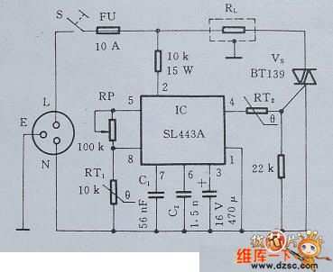
The electric water heaters always use the phase angle control method to control the temperature, that means the electric water heaters use the two-way SCR to control the heating element power's conduction angle of each half cycle. Greater the conduction angle is, longer the conduction time of each half cycle is, so the electric heating elements has the greater average power; otherwise the average power is smaller. This mode makes the load current's conduction and blocking more frequent to produce a large number of harmonics, these harmonics have great disturbance to other home appliances. Here I introduce the full cycle control method's water heater thermostat with automatic control circuit.
1 principle circuit
Figure 1 is the electric water heater thermostat control circuit. Because the RL's conduction and blocking happen in the moment of the voltage is over-zero, and the number of conduction and blocking per second is less than the phase angle control method, so even in the use of high-power electric equipments, there will not have a great interference.
Figure 1 Electric water heater thermostat self-control circuit
2 Selection of the main components
In order to facilitate the adjustment, the electric water heater thermostat self-control circuit uses the potentiometer which has linear resistance characteristics. RT1 uses the PTC thermistor after the line treatment, RT2 uses the 60℃ step-type PTC thermistor. VS is determined by the RL's power, and this circuit's RL is 2KW, the SCR should be equipped with heat sink. (View)
View full Circuit Diagram | Comments | Reading(4499)
voice control duplex wireless interphone circuit
Published:2011/5/3 9:55:00 Author:Christina | Keyword: voice control, duplex, wireless interphone
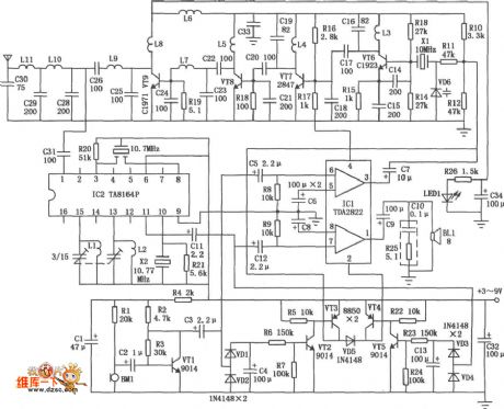
The wireless interphone is in the FM duplex mode, the operating frequency is 30MHz, it uses the voice control electronic switch, the circuit is simple, easy to use and saving energy. The operating voltage is 3 to 9V, the transmitting power is 1~5W.
The voice control duplex wireless interphone has two parts: receiving part and transmitting part (use the antenna matching network together), the circuit is as shown in figure. The transmitting part is composed of the microphone amplifier, electronic switch, oscillation and frequency circuits, incentive amplifier, power amplifier and the antenna matching network. The receiving part is composed of the antenna matching network, the FM receiving circuit, the electronic switch and the amplifier circuit.
(View)
View full Circuit Diagram | Comments | Reading(1440)
| Pages:275/312 At 20261262263264265266267268269270271272273274275276277278279280Under 20 |
Circuit Categories
power supply circuit
Amplifier Circuit
Basic Circuit
LED and Light Circuit
Sensor Circuit
Signal Processing
Electrical Equipment Circuit
Control Circuit
Remote Control Circuit
A/D-D/A Converter Circuit
Audio Circuit
Measuring and Test Circuit
Communication Circuit
Computer-Related Circuit
555 Circuit
Automotive Circuit
Repairing Circuit