
Index 278
Acousto-optic control stair delay switch circuit with operational amplifier
Published:2011/4/28 4:33:00 Author:Nicole | Keyword: acousto-optic control, stair delay switch, operational amplifier
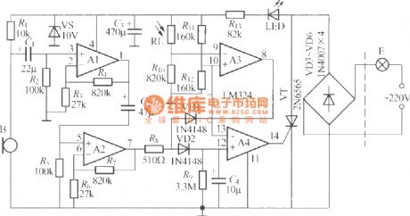
The figure is as shown, it is a acousto-optic control stair delay switch which adopts LM324 operational amplifier, it adopts two-wire system connection, it can replace the ordinary light switch directly, it is not needed to change the indoor original wiring. In figure, the operational amplifier A1~A4 which is connected into four voltage comparator can use a single power supply four operational amplifier IC LM324, theother components are as shown, there is no special requirements. (View)
View full Circuit Diagram | Comments | Reading(703)
Toilet automatic lighting switch circuit composed of CD4022
Published:2011/4/24 1:20:00 Author:May | Keyword: Toilet automatic lighting switch
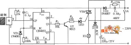
The diagram is Toilet automatic lighting switch which uses gate control type, when someone enter, the door open once, lighting switch breakover, the lamp is lightening. When someone go out the door and open it again, switch cut off and go out. The circuit network is shown in the diagram. The circuit consists of Hall switch, octal count, pulse distributor CD4022 and bidirectional thyristorVTH.
(View)
View full Circuit Diagram | Comments | Reading(3044)
ZKB8711 controlled alarm IC for constant temperature automatic control alarm circuit diagram
Published:2011/4/28 20:29:00 Author:Ecco | Keyword: controlled , alarm , IC , constant temperature , automatic control , alarm
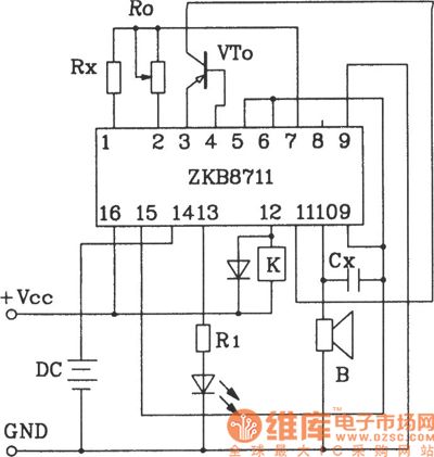
ZKB8711 controlled alarm IC for constant temperature automatic control alarm circuit.
ZKB8711 can be used for temperature control, light control, humidity control, rain and harmful gas detection and alarm control and so on, it has the advantages of several functions, few external components, easy making and so on.
(View)
View full Circuit Diagram | Comments | Reading(1374)
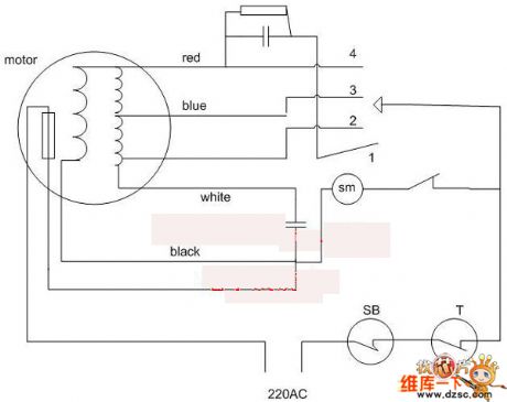
Motor PWM speed control circuit
Published:2011/4/28 18:59:00 Author:Christina | Keyword: motor, PWM, speed control
View full Circuit Diagram | Comments | Reading(561)
Fan automatic switch circuit
Published:2011/4/28 20:09:00 Author:Christina | Keyword: Fan, automatic switch
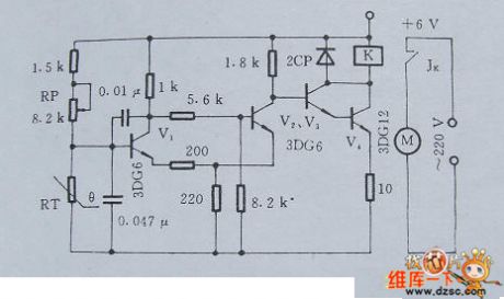
1.Principle circuit
The fan automatic switch circuit is as shown in figure 1. The voltage divider is composed of the PTC thermistor RT and RP, you can set the fan's temperature by regulating the RP.
Figure 1 The fan automatic switch circuit
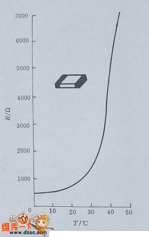
2.Main components
The fan automatic switch circuit uses the PTC thermistor as the RT temperature sensing element, the standard resistance - temperature curve of this device is as shown in figure 2.
Figure 2. the standard resistance - temperature curve
This circuit can be used in wide range of applications such as the warehouse.
(View)
View full Circuit Diagram | Comments | Reading(825)
Car coolant alarm circuit
Published:2011/4/28 18:52:00 Author:Christina | Keyword: Car coolant, alarm circuit
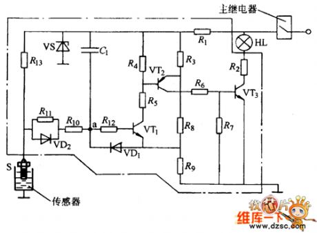
The car coolant alarm circuit is as shown in the figure. If the coolant level is normal, the sensor is grounded through the liquid, in the figure, a point has no voltage level. When switch turns on, level alarm system will check itself. Specific work process is as follows:
(1)Turn on the ignition switch, the main relay starts working. c1 is charged by the high charge current and this current maintains the t1 turns on, t2 turns on, t3 turns on, then the indicator turns on.
(2)When the c1 is full, current is gradually reduced, t1 turns off, t2 turns off, t3 turns off, then the indicator turns off.
The light-time is related with the parameters c1. When this device is checking itself, if the warning light does not shine, it means there is something wrong with the alarm system, you should check it.
(3)If the liquid level is too low, the sensor can not reach the liquid, Point a's voltage level becomes higher, t1 base potential becomes higher too, t1 turns on, t2 turns on, t3 turns on, then the indicator turns on, When this device is checking itself, if the warning light does not turns off, it means the coolant liquid level is too low, you need to fill it.
(4)When the coolant level is normal, if you turn off the switch, c1's charge-circuit is: c1(+)→r1→r11→r10→c1(-). (View)
View full Circuit Diagram | Comments | Reading(1201)
Solid-sense switch circuit to protect person and equipment
Published:2011/4/28 6:10:00 Author:TaoXi | Keyword: Solid-sense switch, protect person and equipment
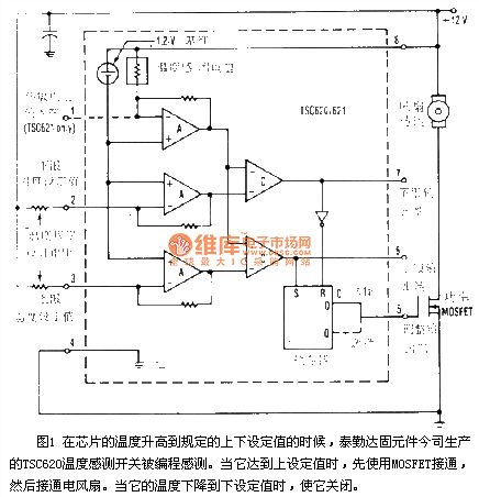
The Solid-sense switch circuit to protect person and equipment is as shown
Figure 1 When the temperature of chip reaches the high set-value or low set-value, the TSC620 temperature sensing switch (produced by the Tai Leda Solid Components Inc.)is sensed by the program. When it reaches the high set-value, MOSFET turns on and then the fan. When it reaches the low set-value, it will shut down. (View)
View full Circuit Diagram | Comments | Reading(468)
Touch delay light circuit with time base circuit (2)
Published:2011/4/27 9:33:00 Author:Nicole | Keyword: Touch delay light, time base
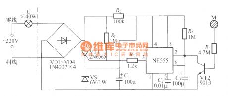
The figure is as shown, it is a touch delay light switch with two-wire system connection and it is composed of NE555 time base circuit, it can directly replace ordinary mechanical switch, and it is no need to change the old wiring. Besides R4, C3 charge time constant, the delay time is also related to the touch time. (View)
View full Circuit Diagram | Comments | Reading(582)
Delay light circuit with digital circuit(1)
Published:2011/4/27 9:28:00 Author:Nicole | Keyword: delay light, digital circuit
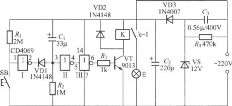
The figure is as shown, it is a delay light with digital IC, in figure, it only uses three good inverters of CD4069, the another three invertersare not used; connecting their input terminal to ground,it caneliminate the interferencewith circuit. K adopts JRX-22F、DC12V small middle power electromagnetic relay. The delay time is determined by the charge time constant of R2, C1. (View)
View full Circuit Diagram | Comments | Reading(765)
Multifunction dimming light circuit with special integrated circuit(HT7706)
Published:2011/4/27 9:23:00 Author:Nicole | Keyword: dimming light
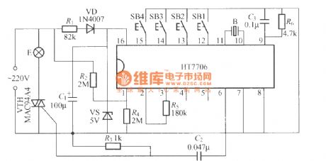
This is a multifunction dimming light circuit with special integrated circuit, it hasfour kinds of dimming functions, they are stepless, step dimming, delay to douse the light and cycle automatic turn-off light. Buses φ27mm ordinary piezoceramics, the other component parameters is as shown, there is no special requirements. (View)
View full Circuit Diagram | Comments | Reading(461)
Smoke alarm circuit composed of MC145010 photoelectric smoke detection alarm integrated circuit
Published:2011/4/28 2:21:00 Author:Ecco | Keyword: Smoke alarm circuit, photoelectric, smoke detection , alarm , integrated circuit

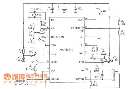
Smoke alarm circuit composed of MC145010 photoelectric smoke detection alarm integrated circuit is shown as the chart. It uses 9V laminated battery. R2, C3 are respectively oscillation resistor and capacitor oscillator, the clock cycle is determined by the follow formula:
(View)
View full Circuit Diagram | Comments | Reading(1757)
touch electrical switch circuit
Published:2011/4/28 1:46:00 Author:TaoXi | Keyword: touch, electrical switch
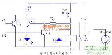
The touch electrical switch circuit.
(View)
View full Circuit Diagram | Comments | Reading(546)
The wiring principle circuit diagram of PLC control pump motor
Published:2011/4/11 2:42:00 Author:may | Keyword: PLC control pump motor
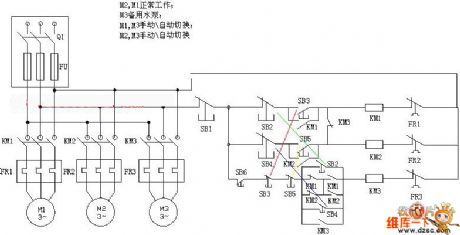
diagram: The wiring principle circuit diagram of PLC control pump motor (View)
View full Circuit Diagram | Comments | Reading(4317)
Remote control type multi-range controller circuit
Published:2011/4/2 4:27:00 Author:may | Keyword: multi-range controller, Remote control
Remote control type multi-range controller circuit is shown in the diagram:
(View)
View full Circuit Diagram | Comments | Reading(534)
The natural wind timing control circuit of electric fan
Published:2011/4/6 5:47:00 Author:may | Keyword: natural wind, timing control, electric fan
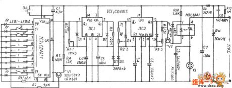
The natural wind timing control circuit of electric fan is shown in the following diagram:
(View)
View full Circuit Diagram | Comments | Reading(588)
Homemade dance mat circuit
Published:2011/4/28 1:19:00 Author:TaoXi | Keyword: Homemade, dance mat
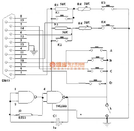
The homemade dance mat circuit.
(View)
View full Circuit Diagram | Comments | Reading(833)
Frequency selection voice control circuit
Published:2011/4/11 2:22:00 Author:may | Keyword: Frequency selection, voice control
Frequency selection voice control circuit is shown in the diagram:
(View)
View full Circuit Diagram | Comments | Reading(499)
Wired remote control water tower telemetry device circuit
Published:2011/4/2 4:29:00 Author:may | Keyword: Wired, remote control, water tower telemetry
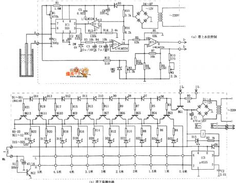
Wired remote control water tower telemetry device circuit is shown in the diagram:
(View)
View full Circuit Diagram | Comments | Reading(1124)
Infrared burglar alarm circuit controlled by SCM
Published:2011/4/6 5:32:00 Author:may | Keyword: Infrared burglar alarm, SCW
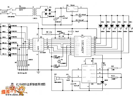
diagram: Infrared burglar alarm circuit controlled by SCM (View)
View full Circuit Diagram | Comments | Reading(1871)
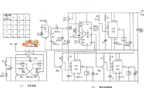
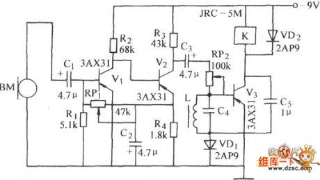
The frequency selection and sound waves remote control switch circuit of fans
Published:2011/4/6 5:34:00 Author:may | Keyword: frequency selection, sound waves remote control, switch, fans
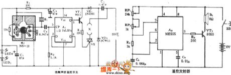
The frequency selection and sound waves remote control switch circuit of fans is shown in the diagram:
(View)
View full Circuit Diagram | Comments | Reading(647)
| Pages:278/312 At 20261262263264265266267268269270271272273274275276277278279280Under 20 |
Circuit Categories
power supply circuit
Amplifier Circuit
Basic Circuit
LED and Light Circuit
Sensor Circuit
Signal Processing
Electrical Equipment Circuit
Control Circuit
Remote Control Circuit
A/D-D/A Converter Circuit
Audio Circuit
Measuring and Test Circuit
Communication Circuit
Computer-Related Circuit
555 Circuit
Automotive Circuit
Repairing Circuit