
Index 279
T type winding tap speed regulation circuit
Published:2011/4/2 4:25:00 Author:may | Keyword: T type, winding tap, speed regulation
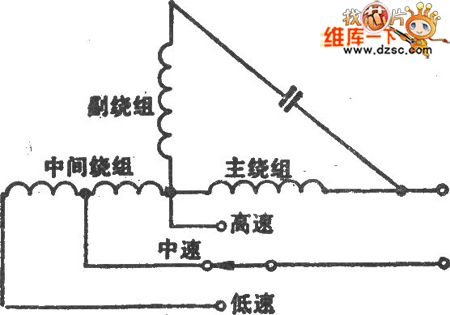
T type winding tap speed regulation circuit is shown in the diagram:
(View)
View full Circuit Diagram | Comments | Reading(446)
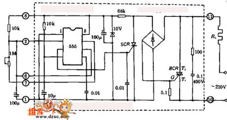
Multipurpose AC electronic switch circuit (for thermoregulation)
Published:2011/4/6 5:36:00 Author:may | Keyword: Multipurpose, AC electronic switch, thermoregulation
View full Circuit Diagram | Comments | Reading(849)
The automatic control circuit of ventilator
Published:2011/4/2 4:35:00 Author:may | Keyword: automatic control, ventilator
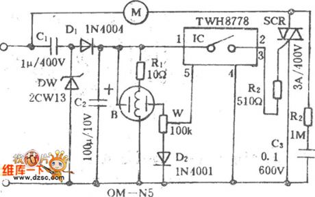
The automatic control circuit of ventilator is shown in the following diagram: (View)
View full Circuit Diagram | Comments | Reading(713)
Multi-controlled three-switch circuit
Published:2011/4/2 4:30:00 Author:may | Keyword: Multi-controlled, three-switch
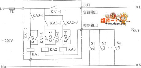
Multi-controlled three-switch circuit is shown in the diagram:
(View)
View full Circuit Diagram | Comments | Reading(587)
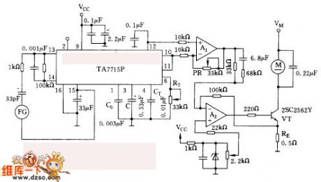
Constant speed control circuit with ta7715p
Published:2011/4/6 5:31:00 Author:may | Keyword: Constant speed control
View full Circuit Diagram | Comments | Reading(1013)
H type winding tap speed regulation circuit
Published:2011/4/2 4:36:00 Author:may | Keyword: H type, winding tap, speed regulation
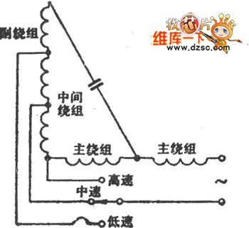
H type winding tap speed regulation circuit is shown in the diagram:
(View)
View full Circuit Diagram | Comments | Reading(453)
PWM Control Dimming Halogen Lamp Circuit
Published:2011/4/27 18:39:00 Author:Christina | Keyword: PWM Control, Dimming Halogen Lamp
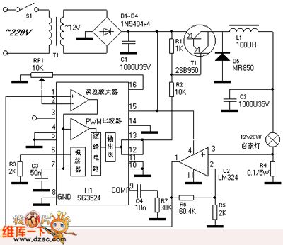
The PWM control dimming halogen lamp circuit is as shown. Rated voltage of the halogen lamp is 12V, the nominal power is 20W, the dimmer circuit can adjust the intensity of halogen lamp from zero to maximum.
Lighting halogen lamp always transforms the frequency electricity (220V or 110V) into 12V AC voltage by using the power transformer. In order to provide operating voltage to the pwm controller sg3524 (ic1) and the op amp lm324 (ic2), the DC voltage will apply to the ic1's 15-pin and 4-pin of ic2. Between the rectifier filter circuit and the halogen lamp, we need to connect the pnp compound transistor vt1 and the vt1 is controlled by the pwm signal of ic1. Through the collector output transistor of vt1, we connect the l1 and c2 to form the lc filter, so we can get the 12V DC voltage to supply power. As the lamp current is 1.67a (20 w/12 v), r4 is 0.1v, the output voltage (5V) sent by ic2's 1-pin will be back to the ic1's 1-pin.
(View)
View full Circuit Diagram | Comments | Reading(4937)
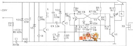
Simple Automatic Emergency Light Circuit
Published:2011/4/27 18:40:00 Author:Christina | Keyword: Simple, Automatic Emergency Light
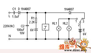
Here is a very simple but very useful emergency light. This device will turn on the small light automatically if the we meet power failure or fuse-cutoff. The circuit uses fewer components, andthis deviceis cheap and simple to make, so it is very suitable for home use.
The circuit is as shown. When the grid is normal, 220V mains voltage is reduced by the capacitor c1, and is half-wave rectified by the diode d, the circuit has the stable DC output voltage (6v) and 90ma output current. The power supplier still supplies power to relay j, the normally close contact point j2-1 disconnects, so hl1, hl2 lost power;on the other hand, the normally open contact point j2-3 disconnects, pulse current float to the battery E.
(View)
View full Circuit Diagram | Comments | Reading(1655)
Simple Timer Circuit Composed Of MC14541
Published:2011/4/27 6:42:00 Author:Robert | Keyword: Simple Timer
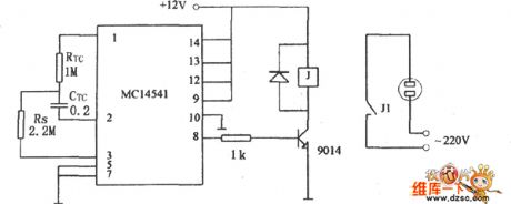
A Simple Timer Circuit conposed of MC14541 is shown below. This Circuit is a simple timing circuit using the IC MC14541. As the parameters shown in the picture, the circuit will time 3 hours, you could choose differential RTC,CRC or Rs value, to get the control of timing you need.
(View)
View full Circuit Diagram | Comments | Reading(3985)
Sub-Ultrasonic Remote Control Switch Circuit
Published:2011/4/27 6:42:00 Author:Robert | Keyword: Sub-Ultrasonic, Remote Control Switch
Sub-Ultrasonic Remote Control Switch Circuit is shown below:
(View)
View full Circuit Diagram | Comments | Reading(604)
Office Electric Heating Plate Automatic Switch Circuit
Published:2011/4/27 6:43:00 Author:Robert | Keyword: Office Electric Heating Plate, Automatic Switch
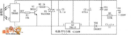
Office Electric Heating Plate Automatic Switch Circuit is shown as below. Based on the normal office desk electric plate heter, it equips the infrared reflection automatical switches composed of the TX50D module, can achieve the goal that automatical power up and heating whenpeople are workingon the plate, and automatic power down and stop heating when nobody there. This circuit could not only save the power, avoid the fash brought by the frequent plugs, but also can extend the life of the office electric heating plate and prevent the occurrence of accidents, it could be connected directly to the normal office electric heating plate, and is easy to produce, stable to work.
(View)
View full Circuit Diagram | Comments | Reading(856)
56M video images transmitting circuit diagram
Published:2011/4/18 1:03:00 Author:Rebekka | Keyword: transmitting circuit, 56M video images
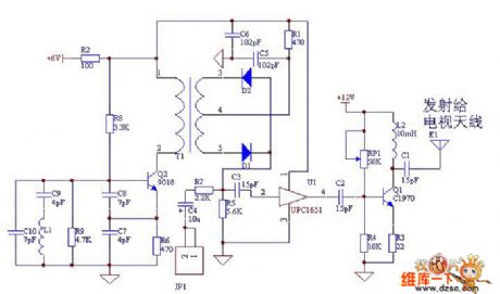
The RF Circuits produce 56MHz frequency through colpitts feedback. The image signal passes camera collection and the internal circuit turns to analog voltage signal. It output from JP1 to diode mixer circuit, mixing circuit will mix the analog voltage signal output by camera with LO signal to form radio-frequency signal. The radio-frequency signal that is amplified by uPC1651 integrated operational amplifier and total emitter circuit will be posted. uPC1651 is TV antenna amplifier ASIC. It is a ultra-high frequency, wide band(Frequency bandwidth of 1200MHz), low noise, large power gain(19dB,f=500MHz), high frequency linear amplifier. (View)
View full Circuit Diagram | Comments | Reading(542)
TC9305-035 logic control system IC circuit
Published:2011/4/26 21:47:00 Author:TaoXi | Keyword: logic control system
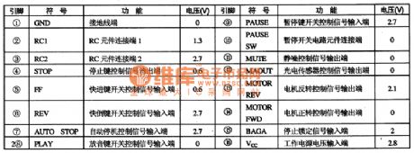
The TC9305-035 is designed as one kind of logic control system IC which is produced by the TOSHIBA company, this device can be used in wide range of applications such as the low voltage walkman, repeater. This device transforms the mechanical switch control signal to the microcomputer circuit.
1. Features
The TC9305-035 integrated circuit is composed of the switch control signal decoding circuit, the squelch control circuit, the motor reverse control circuit.etc.
2. Pin functions and data
TC9305-035 integrated circuit is in the 16-pin dual in-style package, the pin functions and data is as shown in table 1.
Table 1. The pin functions and data of the TC9305-035 (View)
View full Circuit Diagram | Comments | Reading(747)
Motor protector 11
Published:2011/4/27 21:18:00 Author:Ecco | Keyword: Motor protector
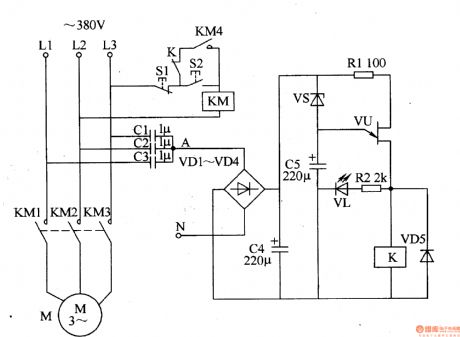
The motor protector described in the example has the protection function of phase auto delay and the features of simple circuit, without an external power supply, and it is suitable for all kinds of automatic (or manual) three-phase AC motor control equipment.
The working principle
The motor circuit protector circuit consists of capacitors CI-C5, diodes VDl-VD5, resistors Rl, R2, zener diode VS, light-emitting diode VL, VU prison junction transistors and relay K, it is shown as Figure 8-47.
When the three-phase power ofLl-L3 being normal, the AC voltage on junction point A of capacitors Cl-C3 will be lower, the voltage is rectified by the VDl-VD4, after being filtered by C4, it is insufficient to turn on VS and VU, K does not pull, the motor M operates normally.
When the three-phase power in the absence of a phase voltage, the place between the zero line and A point will quickly produce l2V AC voltage. This voltage is rectified by VDl-VD4 and filtered by C4, so that making VS breakdown conduction, C5 starts charging, after delaying several seconds (after C5 charging), VU turns, VL is lit, K pulls in, the contacts are off, so that the AC contactor KM releases, cutting off the working power source of motor M.
When the three-phase power is restored to normal, after a short delay, VU is off, K releases, then you can press the start button S2 to restart the motor. (View)
View full Circuit Diagram | Comments | Reading(1298)
Photoelectric alarm circuit diagram
Published:2011/4/19 22:33:00 Author:Rebekka | Keyword: Photoelectric alarm
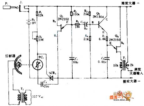
When light beam I1 and photocell between the PC1 are truncated, they will start the alarm circuit resulting in a special scanning a single audio signal. This signal is sent to a simple amplifier with amplified speakers. It will make an alarm signal. When the light I1 is truncated, PC1 resistance will become larger, SCR1 will be turned on, so that the negative power supply terminal B1 and the circuit in the back of SCR1 can be connected. Q1, Q3 are two single-junction transistor. They are used as oscillator components in the circuit. R3, C1 determine the oscillation frequency of Q1; R3, C3 determine the oscillation frequency of Q3; Q2 for amplification. The light and the photocell of the circuit can be placed on the door or window of the opposite sides of the mirror to collect light in the room.
(View)
View full Circuit Diagram | Comments | Reading(1084)
Motor protector 10
Published:2011/4/27 20:49:00 Author:Ecco | Keyword: Motor protector
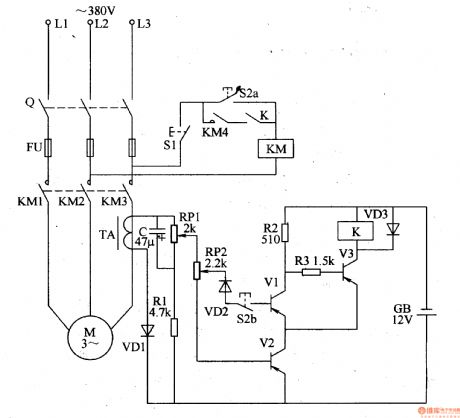
The motor protector described in the example can cut off the power supply when any phase of power in three-phase AC motor being lacking, it can prevent winding overheating damage due to broken phase operation.
The working principle
The motor protector circuit is composed of the voltage detection circuit and protection controlling execution circuit, it is shown as Figure 8-46.
Starting control circuit is composed of stopping button Sl, starting button S2 and AC contactor KM (the original motor starting circuit).
Voltage detection circuit is composed of the diodes VDl-VD3, Zener diode VSl-VS3, resistors Rl-R6, capacitors Cl-C3 and optocouplers VLCl-VLC3.
Protection control circuit consists of transistors V, relay K, the diode VD4 and resistor R7.
Rl, R3 and R5 use 1-2W metal film resistors; R8, R4, R6 and R7 use 1/4W carbon film resistors or metal film resistors.
Cl-C3 select aluminum electrolytic capacitors with voltage in 16V.
VDl-VD4 use 1N4007 silicon rectifier diodes.
VSl-VS3 select lW, 9 · IV silicon voltage regulator diodes.
V uses S8050, 3DG805O, BC136 or other models NPN silicon transistors.
VLCl-VLC3 use 4N25 or MCT2E, TL206 coupler.
K uses 9V DC relay. (View)
View full Circuit Diagram | Comments | Reading(2011)
Six-way each reset type touch switch circuit
Published:2011/4/27 20:43:00 Author:Nicole | Keyword: touch switch
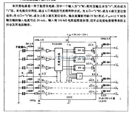
This switch circuit is a touch switch circuit, if one of inputs is 0 , then the corresponding output is 0 , the others are 1 . This circuit has two groups, the selection control can achieve two ways by 6/3 terminal. When 6/3= 1 , it will become six-way each reset type action; when 6/3= 0 , it will become two groups three-way each reset type action. The output is open drain(N ditch)type, when VDD=12V, the input current of all kinds output terminal can reach 30mA. Input terminal 100kΩ current takes the action of limiting current, but it is no need to connect capacitance to prevent wobble and other error trigger. (View)
View full Circuit Diagram | Comments | Reading(963)
TC9OA49D digital comb filter Y/C separate circuit
Published:2011/4/27 10:01:00 Author:TaoXi | Keyword: digital, comb filter, Y/C separate
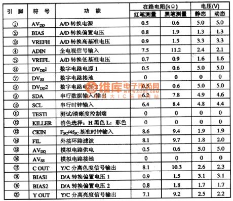
The TC9OA49D is designed as one kind of digital comb filter Y/C separate circuit which is produced by the TOSHIBA company, and this device can be used in domestic and imported new large-screen color TV.
The TC9OA49D is in 20-pin dual in-line package, the pin functions and data is shown in table 1. The data is from the Haier Baodelong large screen color TV.
Table 1 The pin functions and data of TC9OA49D (View)
View full Circuit Diagram | Comments | Reading(503)
AC timer switch control circuit composed of μA7555
Published:2011/4/27 4:00:00 Author:TaoXi | Keyword: AC, timer switch control
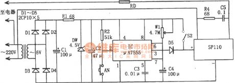
The AC timer switch control circuit is as shown:
(View)
View full Circuit Diagram | Comments | Reading(567)
Using SL as gas leak detector circuit diagram
Published:2011/4/27 3:37:00 Author:Rebekka | Keyword: gas leak detector
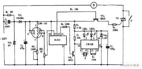
Using SL as gas leak detector circuit diagram is shown as above. (View)
View full Circuit Diagram | Comments | Reading(3143)
| Pages:279/312 At 20261262263264265266267268269270271272273274275276277278279280Under 20 |
Circuit Categories
power supply circuit
Amplifier Circuit
Basic Circuit
LED and Light Circuit
Sensor Circuit
Signal Processing
Electrical Equipment Circuit
Control Circuit
Remote Control Circuit
A/D-D/A Converter Circuit
Audio Circuit
Measuring and Test Circuit
Communication Circuit
Computer-Related Circuit
555 Circuit
Automotive Circuit
Repairing Circuit