
Index 266
Op-amp parallel circuit
Published:2011/5/16 4:19:00 Author:Christina | Keyword: Op-amp, parallel
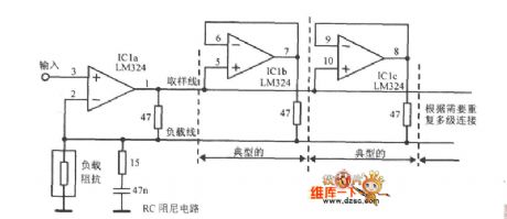
The Op-amp parallel circuit is as shown:
(View)
View full Circuit Diagram | Comments | Reading(1448)
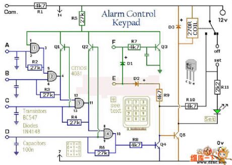
4-channel keyboard control circuit
Published:2011/5/16 3:33:00 Author:Christina | Keyword: 4-channel, keyboard, control circuit
View full Circuit Diagram | Comments | Reading(741)
Low-pass filter circuit
Published:2011/5/16 3:29:00 Author:Christina | Keyword: Low-pass, filter
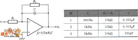
The Low-pass filter circuit is as shown:
(View)
View full Circuit Diagram | Comments | Reading(850)
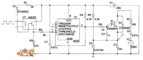
IGBT drive circuit diagram composed of 555 timer
Published:2011/5/13 1:11:00 Author:Nicole | Keyword: IGBT drive, 555 timer
View full Circuit Diagram | Comments | Reading(3769)
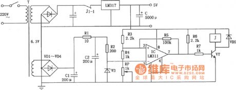
Automatic adjustment type controller circuit diagram
Published:2011/5/13 2:59:00 Author:Rebekka | Keyword: Automatic adjustment type, controller
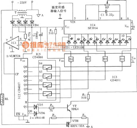
The temperature controller can automatically adjust the electric heater input power while it is using light-emitting diode to display the temperature range. It keeps the controlled heater work at a constant temperature working condition. (View)
View full Circuit Diagram | Comments | Reading(745)
Thermal protection system circuit composed of MIC2951
Published:2011/5/12 20:52:00 Author:Rebekka | Keyword: Thermal protection system
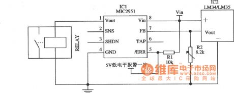
Thermal protection system circuit composed of MIC2951 is shown as above. The temperature threshold of the circuit is set by the adjustment of R2. (View)
View full Circuit Diagram | Comments | Reading(689)
Humidity Sensor Interface Circuit
Published:2011/5/15 5:46:00 Author:Michel | Keyword: Humidity Sensor, Interface Circuit
View full Circuit Diagram | Comments | Reading(734)
IX0689 switch power supply circuit
Published:2011/5/15 5:10:00 Author:John | Keyword: switch
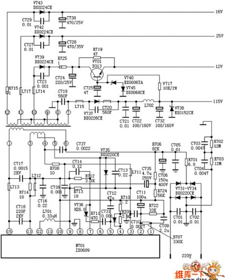
IX0689 switch power supply circuit is given in the following.
(View)
View full Circuit Diagram | Comments | Reading(593)
High-speed voltage follower circuit
Published:2011/5/15 3:37:00 Author:John | Keyword: High-speed voltage follower
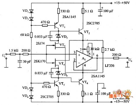
The figure is a high-speed voltage follower circuit. The circuit is constituted by the VT3 and VT4. Al is the voltage follower circuit, which is constituted by the pin 7 of A1 and pin 4 of VT2 and VT6. Pin 7 of and pin 4 are just level shifting positions of the input signal voltage. Therefore, when the input signal is large, the power supply voltage on all-aspect of A1 and output end remains constant about 5V. As signal current through phase compensation capacitor from the Al-chip surges, the conversion rate has been greatly improved and high frequency distortion has been significantly reduced.
(View)
View full Circuit Diagram | Comments | Reading(1167)
Power supply over voltage detection and time delay protection circuit diagram
Published:2011/5/16 3:19:00 Author:Rebekka | Keyword: over voltage detection , time delay protection
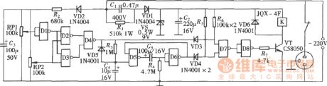
For some electrical equipments, the operating supply voltage range is strictly limited. Over-voltage or under-voltage will affect the work or even damage the equipment. The following shows a over-voltage and under voltage detection and time delay protection circuits. It can cut off the power supply when it is over-voltage or under-voltage. And it can start automatically after a period of delay. It is composed of two four-two input NAND gates CD4011. The over voltage and under-voltage detection circuit is composed of D1-D3 and RPl, RP2. D4 is trigger circuit. The relay driver circuit is composed of D7, D8 and transistor VT. The time relay restart circuit is composed of D5, D6 and R4, C5. (View)
View full Circuit Diagram | Comments | Reading(1777)
bridge amplifier circuit with a low-noise compensation circuit
Published:2011/5/15 2:02:00 Author:John | Keyword: low-noise compensation circuit, bridge amplifier
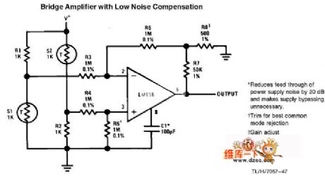
bridge amplifier circuit with a low-noise compensation circuit
(View)
View full Circuit Diagram | Comments | Reading(1069)
Home appliances overvoltage protector circuit diagram
Published:2011/5/15 5:55:00 Author:Rebekka | Keyword: Home appliances , overvoltage protector
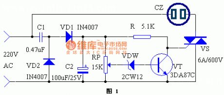
When the voltage suddenly rises because of some reason,household appliances such as the running refrigerators, washing machines, televisions, stereos, computers will face varying degrees of damage, even catch serious fire, causing great economic loss. This paper describes a simple over-voltage protection device, which provides protective effects on the appliance. When the voltage exceeds the allowable range, thepower supply will automatically cut off. Once the voltage turns to normal, the power can be automatically switched back. (View)
View full Circuit Diagram | Comments | Reading(2038)
non-inverting AC amplifier circuit
Published:2011/5/15 2:59:00 Author:John | Keyword: AC amplifier
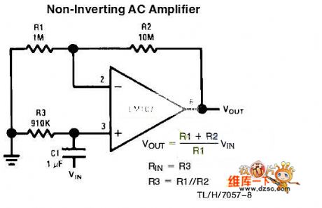
Non-inverting AC amplifier circuitis shown below.
(View)
View full Circuit Diagram | Comments | Reading(3259)
inverting amplifier with high input impedance circuit
Published:2011/5/15 2:38:00 Author:John | Keyword: inverting amplifier
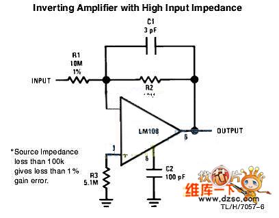
Inverting amplifier with high input impedance circuit is shown below.
(View)
View full Circuit Diagram | Comments | Reading(2061)
Reset circuit
Published:2011/5/15 2:40:00 Author:John
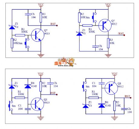
Reset circuit is shown below.
(View)
View full Circuit Diagram | Comments | Reading(927)
A3 switch power supply circuit
Published:2011/5/15 2:54:00 Author:John | Keyword: A3 switch
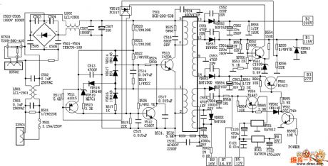
A3 switch power supply circuit is shown below.
(View)
View full Circuit Diagram | Comments | Reading(710)
Frost Alarm (2)
Published:2011/5/14 4:13:00 Author:Sue | Keyword: Frost, Alarm
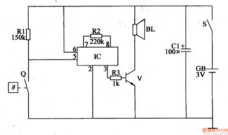
Working Principle:
As seen in the figure 4-110, the frost alarm circuit consists of power circuit, temperature detection controlled circuit and alarm circuit.
When S is connected, the alarm circuit prepares to work. When the temperature is higher than 1℃, Q is disconnected and the alarm circuit doesn't work, and BL makes no sound. When the temperature is lower than1℃, Q is connected and IC begins to work. IC's 3 pin will output audio electric signal, which will promote BL to make a warning sound after the signal is amplified by V. (View)
View full Circuit Diagram | Comments | Reading(774)
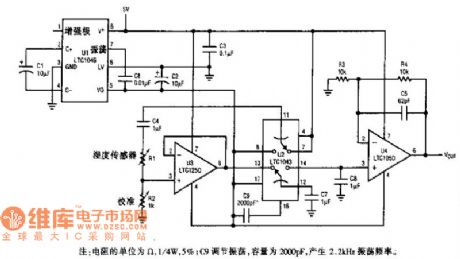
5082-4350 Automatic amplitude control circuit diagram with optical isolation
Published:2011/5/13 3:28:00 Author:Ecco | Keyword: Automatic amplitude , control circuit, optical isolation
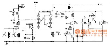
The circuit has a long time frequency stability, temperature changes can be ignored, and it eliminates the pulse load on the frequency, the oscillator uses emitter coupled circuit and 2N3707 low-noise transistor. In addition, it is also given the output amplifier and automatic amplitude control circuit. This circuit is designed for ham using radio equipment.
(View)
View full Circuit Diagram | Comments | Reading(949)
SBC overvoltage protection circuit diagram
Published:2011/5/15 5:14:00 Author:Rebekka | Keyword: SBC overvoltage protection
The circuit is shown as above. It can use +5 V operating voltage SBC power supply. It can prevent the damage of the SBC to +5 V the entire SBC because of overvoltage. (View)
View full Circuit Diagram | Comments | Reading(756)
Optically isolated input protection circuit diagram
Published:2011/5/13 1:31:00 Author:Ecco | Keyword: Optically , isolated , input , protection
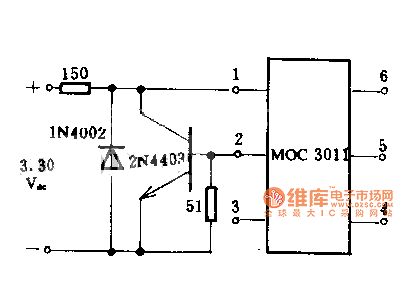
Diodes and transistors form the circuit, when the input voltage range is 3 ~ 30V DC, the input current of MOC3011 optical isolator LED is limited to be less than the safety limit of 15mA. In the case of reverse polarity accident, the circuit can protect the light-emitting diodes.
(View)
View full Circuit Diagram | Comments | Reading(1157)
| Pages:266/312 At 20261262263264265266267268269270271272273274275276277278279280Under 20 |
Circuit Categories
power supply circuit
Amplifier Circuit
Basic Circuit
LED and Light Circuit
Sensor Circuit
Signal Processing
Electrical Equipment Circuit
Control Circuit
Remote Control Circuit
A/D-D/A Converter Circuit
Audio Circuit
Measuring and Test Circuit
Communication Circuit
Computer-Related Circuit
555 Circuit
Automotive Circuit
Repairing Circuit