
Index 263
Pyroelectric infrared sensing automatic door control and voice calling circuit HN911D
Published:2011/5/11 19:03:00 Author:TaoXi | Keyword: Pyroelectric, infrared sensing, automatic door control, voice calling
The circuit is as shown. It is composed of the pyroelectric infrared sensor module, the delay control network, the electric coupling & SCR control circuit, the language voice circuit, the AC step-down rectifier circuit.etc. The HN911D is one kind of pyroelectric infrared detector module. (View)
View full Circuit Diagram | Comments | Reading(836)
Motor electronic governor controller 6
Published:2011/5/17 21:18:00 Author:Nicole | Keyword: Motor, electronic governor controller
The circuit work theory
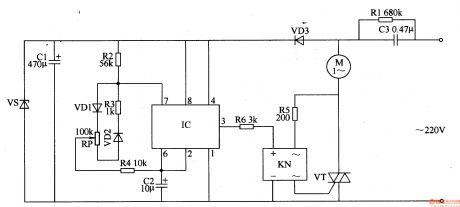
This motor electronic governor controller circuit is composed of power supply circuit, ultralow-frequency oscillator and control implement circuit, the circuit is shown in the figure 8-63.
The power supply circuit is made of depressurization capacitor C3, bleeder resistor R1, rectifier diodes VD3, filter capacitors C1 and steady voltage diode VS.
The ultralow-frequency oscillator consists of time base integrated circuit IC, resistors R2-R4, potentiometers RP, capacitor C2 and diodes VD1, VD2.
The control implement circuit is composed of solid state relay KN(SSR)、transistor VT and resistor R6.
(View)
View full Circuit Diagram | Comments | Reading(1685)
Over-voltage over-current protector
Published:2011/5/18 4:24:00 Author:TaoXi | Keyword: Over-voltage, over-current, protector
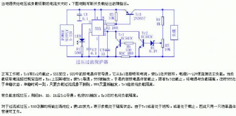
In the normal working hours, Tr1 and Tr2 are cut-off, 555 is reset, and the discharge transistor of the 555 is conducted, it absorbs the current from Tr3's base electrode to make Tr3 saturated, the 5~12V power directly sends to the main load. When the load absorbs too much current, Rsc's pressure drop increases, the Tr1 conducts and 555 is triggered, so the internal discharge transistor cuts off, then the Tr3. At this time, the 555 is in the single stable state, when the single stable time is up, as long as the load over-flow phenomena is not ruled out, 555 will be triggered again, Tr3 will continue separate the load.
(View)
View full Circuit Diagram | Comments | Reading(878)
Excellent performance city electricity over-voltage protection circuit
Published:2011/5/18 3:13:00 Author:TaoXi | Keyword: Excellent performance, city electricity, over-voltage protection
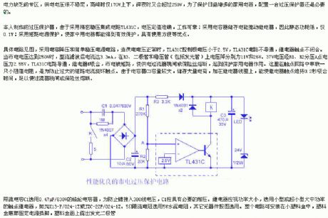
The circuit is as shown, this circuit uses the capacitance step-down and simple manostat circuit, when the power supply voltage is normal, the TL431C control pole voltage is less than 2.5V, TL431C circuit is not conduction, the relay contact point is not close. When the city electricity voltage is 250V, the rectifier & filtering current is 3.3mA, the voltage drop of R3 is 11V and the voltage drop of the diode and regulator tube (including the glowing tube) are 26V and 37V. The voltage is separated by R1 and R2, point A's voltage is 2.55V, the TL431C circuit is conduction, and relay K closes, the city electricity becomes the short-circuit to make the power supply current flowing device tripping or the fuse fusing, so this circuit protects the household appliances.
(View)
View full Circuit Diagram | Comments | Reading(1689)
Washing machine electronic timer circuit
Published:2011/5/17 21:50:00 Author:TaoXi | Keyword: Washing machine, electronic timer
Washing machine electronic timer circuit (View)
View full Circuit Diagram | Comments | Reading(698)
Practical double-watch timing circuit (4)
Published:2011/5/17 22:03:00 Author:TaoXi | Keyword: Practical, double-watch, timing circuit
Related components PDF download:
9014
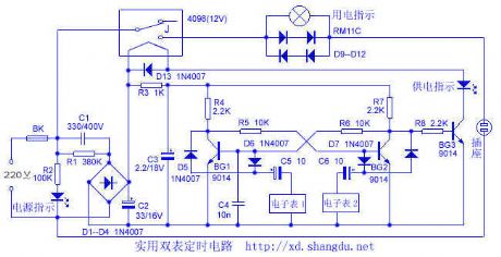
The circuit principle is as shown. After the process of buck, rectifier, filtering, this circuit supplies the working power supply to the control circuit. The bi-stable circuit is composed of the BG1 and BG2 and other external components, they work in the switching state. The control switch is composed of the BG3 and the relay to control the output of the AC 220V voltage. Both of the digital watches have the functions of point timekeeping and music button, they connect to the control circuit by using their two voice signal output line. Electronic watch 2 responsible for open, when it outputs the music electrical signal, the circuit cuts off BG2 by C6 and D7, at this time BG1 conducts to maintain this state. (View)
View full Circuit Diagram | Comments | Reading(998)
Gas water heater optical coupling self-control exhaust fan circuit
Published:2011/5/17 9:31:00 Author:TaoXi | Keyword: Gas water heater, optical coupling, self-control, exhaust fan
The Gas water heater optical coupling self-control exhaust fan circuit is as shown: (View)
View full Circuit Diagram | Comments | Reading(450)
three-phase motor overheating fault phase protection circuit
Published:2011/5/17 9:20:00 Author:TaoXi | Keyword: three-phase, motor, overheating, fault phase, protection circuit
The three-phase motor overheating fault phase protection circuit is as shown: (View)
View full Circuit Diagram | Comments | Reading(573)
Double-bit temperature controller circuit
Published:2011/5/17 9:13:00 Author:TaoXi | Keyword: Double-bit, temperature controller
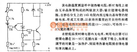
This circuit's temperature measuring bridge is connected to the thermistor, the bridge diagonal is connected to the two-stage amplifier which is composed of the complementary transistor, the output port is connected to the relay coil. The emitter current of the output transistor gets through the 10Ω resistance of the bridge's right branch to form the positive feedback to gain the switching characteristic and the hysteresis. Select the appropriate feedback resistor values (0 to 100Ω), you can get the 0 to 3% wide hysteresis.
(View)
View full Circuit Diagram | Comments | Reading(439)
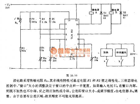
Three-bit temperature controller circuit
Published:2011/5/17 8:50:00 Author:TaoXi | Keyword: Three-bit, temperature controller
Related components PDF download:
TCA965
This circuit uses the thermistor RH, it's nonlinear characteristics can be changed into the linear characteristics by R1 and R2. In the three states of the relay control, the window size adjustment depends on the halfway point of the window and the half width. If the input voltage UE is in the window, the circuit is neither heating nor cooling. Otherwise, it should be heating or cooling. The tolerance is the window size or the mediate precision, it is adjusted by the potentiometer RP2. Because there must be the tolerance zone, so the precision may not infinitely improved.
(View)
View full Circuit Diagram | Comments | Reading(782)
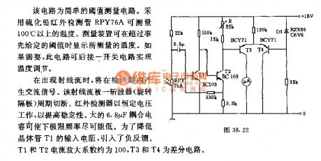
Measurement and temperature control circuit uses the infrared group inspection device
Published:2011/5/17 19:07:00 Author:TaoXi | Keyword: Measurement, temperature control, infrared group inspection
Related components PDF download:
BC109BCY71
The ray stream will produces the AC signal in the detector. And this ray stream will be cut off by the chopper's (rotary separator) cycle. The infrared detector is working with the constant voltage to improve the stability. The big 6.8pF coupling capacitor can make the floor frequency lower and lower. In order to reduce the transistor T1's input resistance, we pull in the negative feedback. T1 and T2's current amplification coefficient is about 100, T3 and T4 are the differential circuit.
(View)
View full Circuit Diagram | Comments | Reading(498)
Motor electronic speed controller circuit diagram 4
Published:2011/5/18 6:51:00 Author:Lucas | Keyword: Motor , electronic speed controller
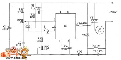
The motor speed controller circuit consists of power circuit, timing control / trigger pulse generator circuit and control implementation circuit, the circuit is shown as the chart. Power supply circuit consists of step-down capacitor C5, voltage regulator diode VS, rectifier diode VD2, filter capacitor C1. Timer control / trigger pulse generator circuit is composed of the time-base integrated circuit IC, the control switch S1, timer / voltage selecting switch S2, resistors R1 ~ R3, potentiometers RP1, RP2, capacitors C2 ~ C4. Control implementation circuit is composed of the resistor M and thyristor VT. AC 220V voltage is bucked by C5, stabilized by resistor R5, VS, rectified by VD2 and filtered by C1 to provide 121V (Vcc) DC working voltage for IC. R1 ~ R5 use 1/4W carbon film resistors or metal film resistors.
(View)
View full Circuit Diagram | Comments | Reading(4244)
Motor electronic speed controller circuit diagram 5
Published:2011/5/18 6:43:00 Author:Lucas | Keyword: Motor , electronic speed controller
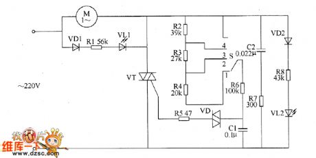
The motor electronic speed controller circuit consists of intergranular tube VT, diode VD1, VD2, bidirectional trigger diode VD, LEDs VL1, VL2, capacitors GI, C2, resistors R1 ~ R8, speed control switch S, motor M and so on, the circuit is shown as the chart. Changing the gear of S speed switch can change the charging and discharging rate of capacitor C1, thereby the thyristor conduction angle of thyristor VT is changed. The voltage on the two ends of C1 can trigger VT and make it turn on by VD, the AC voltage across the motor M is controlled by changing the conduction angle, thus the M's running speed is changed. VL1 and VL2 are the working status indicator LEDs. When S is placed on the 1 block, VL2 is lit; when the S is placed on the 4 block, VL1 is lit.
(View)
View full Circuit Diagram | Comments | Reading(1192)
Motor electronic speed controller circuit diagram 6
Published:2011/5/18 6:20:00 Author:Lucas | Keyword: Motor , electronic speed controller
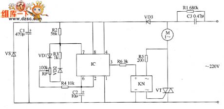
The motor speed controller circuit consists of power circuit, ultra-low frequency oscillator circuit and control implementation circuit, the circuit is shown as the chart. Power supply circuit consists of step-down capacitor C3, discharging resistor R1, rectifier diode VD3, filter capacitor C1 and Zener diode VS. Ultra-low frequency oscillator is composed of time-base integrated circuit, resistor R2 ~ R4, potentiometer RP, capacitors C2 and diodes VD1, VD2. Control implementation circuit is composed of a solid state relay KN (SSR), thyristor VT and resistors R5, R6. AC 220V voltage is bucked by C3, rectified by VD3, filtered by C1 and stabilized by vs to provide +12 V operating voltage for IC. When ultra-low-frequency oscillator gets power and works, the IC output frequency from pin 3 of IC is about 1Hz ultra-low frequency pulse signal.
(View)
View full Circuit Diagram | Comments | Reading(2088)
The engine power-control system circuit of Tianjin Toyota 8A-FE
Published:2011/5/17 22:36:00 Author:Borg | Keyword: power-control systemToyota
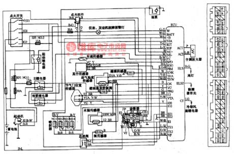
Tianjin Automobile Industry launched the Xiali TJ7131U at the turn of the century, which is fixed with the 8A-FE engine produced by Tianjin Toyota Corp.. The engine has 4 cylinders and 16 valves, power controlled petrol multiple jets, dual overhead camshafts, closed-loop control and triple catalysis transformers, the emission is 1.31L, rated output power is 63kW/6000rpm, and the largest torque is 1lON·m/5200rpm。
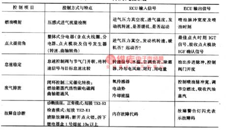
Like other power jet engine, the control system of 8A-FE can also control the stableness of idle speed, the pollution of exhaust and fault detection, etc.
(View)
View full Circuit Diagram | Comments | Reading(1578)
Motorcycle burglar alarm circuit diagram
Published:2011/5/17 19:41:00 Author: | Keyword: Motorcycle, burglar alarm
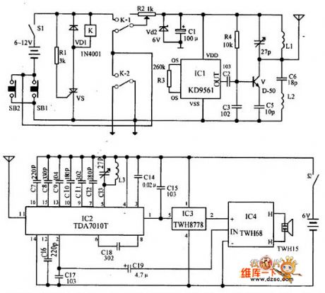
Transmitter: the relay K and SCR VS are used to control the power of transmitter circuit. IC1 forms alarm sound signal circuit. The transistor V and its peripheral components form RF oscillator circuit to transmit the alarm signal. When the circuit is in the waiting state, the switch S1 is connected, and SB1 is disconnected(the front lock is locked), K is in the release state, the alarm transmitter does not work. When the front lock is opened (SB1 is connected), VS is triggered and turned on, K pulls in, the transmitter gets power. When SB1 is switched on, the normal open point of K-2 will be self-locking, at this time, the S1 being disconnected can stop the alarm.
(View)
View full Circuit Diagram | Comments | Reading(2254)
Water Level Indicator (3)
Published:2011/5/17 20:41:00 Author:Sue | Keyword: Water Level, Indicator
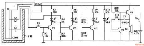
When water level is lower than L, VL1-VL3 are not illuminated.
When the level reaches L, V1 will have a high level, making VL1 illuminated, indicating that the level has reached 1/3.
When water level reaches M, VL2 is illuminated.
When the level reaches H,VL3 is illuminated, indicating the water case is full. At the same time, audio oscillator begins to work, forcing BL to make a warning sound to inform the users. (View)
View full Circuit Diagram | Comments | Reading(2469)
Water Level Indicator (2)
Published:2011/5/17 20:38:00 Author:Sue | Keyword: Water Level, Indicator
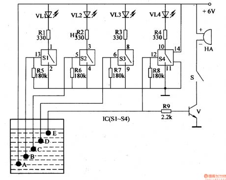
When there is no water, VL1-VL4 are not illuminated.
When water level reaches 1/4, IC’s 13 pin will have a high level, which will make S1 connected. VL1 is illuminated. As water level becomes higher, VL2-VL4 will be illuminated one by one.
When the water case is full, IC’s 12 pin will have a high level, which will make VM illuminated. S will be connected and forces HA to make a warning sound. (View)
View full Circuit Diagram | Comments | Reading(3402)
Water Level Indicator (1)
Published:2011/5/17 20:34:00 Author:Sue | Keyword: Water Level, Indicator
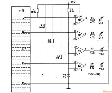
When there is no water, N1-N4’s reverse input terminal will have a voltage which is higher than +5V base voltage, so N1-N4 will output low level, and VL1-VL4 are not illuminated.
When water level reaches D, N1’s reverse input terminal’s voltage will be lower than +5V, N1 outputs high level and illuminates VL4, indicating that water level reaches D.
As the water level becomes higher, N2,N3,N4 outputs high level one by one, and VL3,VL2,VL1 is illuminated one by one.
When VL1-VL4 are all illuminated, users will turn off the suction pump. (View)
View full Circuit Diagram | Comments | Reading(3858)
Water Level Detector
Published:2011/5/14 3:48:00 Author:Sue | Keyword: Water Level, Detector
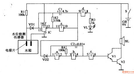
When the water doesn't reach the certain water level, the water level sensor doesn't work. A voltage of +9V will be provided to VD1, making IC's 13,10,1,4 pins have high level, and the alarm circuit doesn't work.
When the water reach the certain level, the sensor begins to work, making VD1's positive pole have low level, and VD1 becomes disconnected. Then the blocking oscillator begins to work, and IC's 10 pin outputs the oscillate signal with a long peried. When the signal voltage is positive, VD2 is connected, IC's 1 pin has high level, and the audio oscillator doesn't work. When the voltage is negative, VD2 is disconnected, and the oscillator begins to work. So the oscillator will work under the control of the blocking oscillator, and IC's 6 pin will output interrupted signals which will promote BL to make a warning sound. (View)
View full Circuit Diagram | Comments | Reading(1814)
| Pages:263/312 At 20261262263264265266267268269270271272273274275276277278279280Under 20 |
Circuit Categories
power supply circuit
Amplifier Circuit
Basic Circuit
LED and Light Circuit
Sensor Circuit
Signal Processing
Electrical Equipment Circuit
Control Circuit
Remote Control Circuit
A/D-D/A Converter Circuit
Audio Circuit
Measuring and Test Circuit
Communication Circuit
Computer-Related Circuit
555 Circuit
Automotive Circuit
Repairing Circuit