
Index 270
TC9153P electronic volume control IC
Published:2011/4/26 22:34:00 Author:TaoXi | Keyword: electronic volume, control IC
The TC9153P is designed as one kind of C(2)MOS Tsz volume control integrated circuit, it can be used in the audio equipment to control the electronic volume .
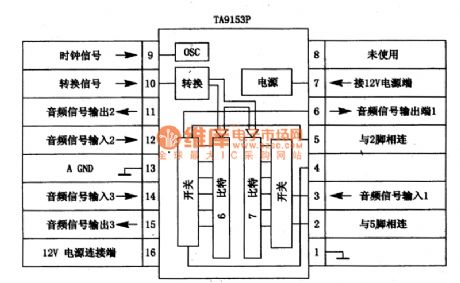
1.TC9153P circuit block diagram and pin functions
The TC9153P is composed of the clock oscillation circuit, conversion circuit, electronic switch circuit, 6-bit and 7-bit circuit.etc, the TC9153P circuit block diagram and pin functions is as shown:
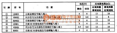
Table 1. The TC9153P circuit block diagram and pin functions.
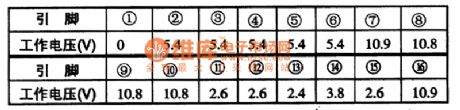
The TC9153P integrated circuit is in the 16-pin dual in-line package, the operating voltage of every pin is as shown in table 1.
Table 1. The operating voltage of TC9153P.
2.TC9153P main electrical parameters
The TC9153P IC supply voltage range is 5 to 12V; in the condition of Vcc=l2V, Vss=0V, Ta=25 ℃, the electrical parameters are as shown in table 1. Both of the IC's positive and negative (+,-) or single power supplier can supply power: as a result of the C (2) COM structure, this device has wide operating voltage range and low current consumption (Vcc=5-12V,IDD=1-3mA).
3.TC9153P typical application crcuit
The TC9153P can be used with the microprocessor TC915OP, so the TC9153P and TC915OP has the same typical application circuit.
4.The circuit working process
The TC9153P controls the attenuation by the internal oscillator and the increase / decrease pin, control range is 0 to 68dB and divide into 32 levels (per 2dB).
Table2. TC9153Pmainelectricalparameters
5.Fault tips
If there is little or no volume, you can use a 10μF capacitance to link the pin-3 and pin-6 of TC9153P, if the voice return to normal, means the TC9153P has interal damage. (View)
View full Circuit Diagram | Comments | Reading(1305)
Household gas alarm circuit
Published:2011/5/8 6:49:00 Author:TaoXi | Keyword: Household, gas, alarm
The Household gas alarm circuit is as shown:
(View)
View full Circuit Diagram | Comments | Reading(539)
TA8851CN I2C bus control switch IC
Published:2011/5/9 2:58:00 Author:TaoXi | Keyword: I2C, bus control switch
The TA8851CN is designed as one kind of I2C bus control switch IC that is produced by the TOSHIBA company, and it can be used in video, audio, multi-channel signal switching and control applications.
1.Features
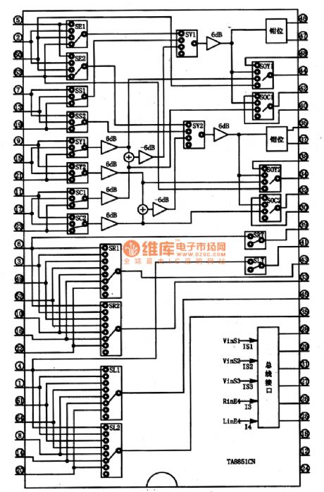
The TA8851CN has the multi-channel electronic switch circuit, the I2C bus interface circuit and the mute control circuit.etc. The block diagram of the circuit is as shown in figure 1.
2.Pin functions and data
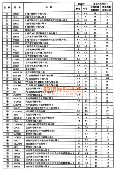
The TA8851/CN is in the 54-pin package, and it can be used in large screen color TV. As the TV/AV/S switch, the pin functions and data of this circuit is as shown in table 1.
Tip: If you want to check the fault leaves, you can use the oscilloscope to check if the different signal's input port and corresponding output port both have thesignals, so you can ensure if the electronic switch is damaged.
Figure 1 The in-circuit block diagram of the TA8851N
Table 1 The pin functions and data of the TA8851CN (View)
View full Circuit Diagram | Comments | Reading(1162)
PTC without-water side-thermal mode circuit
Published:2011/5/8 18:43:00 Author:Christina | Keyword: PTC, without-water, side-thermal mode
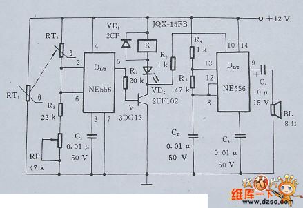
The PTC without-water and over-temperature control side-thermal mode circuit is composed of the detection, control, alarm and other components, the circuit is as shown in figure 1. When there is no water or the water temperature exceeds a set value, RT1's resistance increases and passes to RT2, RT2's resistance also increases after heated, this makes the U1<4V. so ⑤'s output becomes high-level voltage, V conducted and VD2 sends out the red indication, relay K's normally closed contact-point cuts off, and switches off the power immediately, at the same time, the alarm works, BL sends out the voice to achieve the dual purposes of alarm and power off.
Figure 1. The PTC without-water and over-temperature control side-thermal mode circuit (View)
View full Circuit Diagram | Comments | Reading(573)
The Band-pass filter circuit which is composed of the amplifier
Published:2011/5/10 22:40:00 Author:Christina | Keyword: Band-pass filter, amplifier
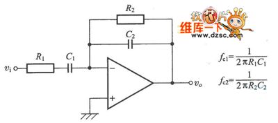
The Band-pass filter circuit which is composed of the amplifier is as shown:
(View)
View full Circuit Diagram | Comments | Reading(537)
High reliable programmable integrated temperature controller TMP01 circuit diagram
Published:2011/5/10 22:12:00 Author:Nicole | Keyword: temperature controller
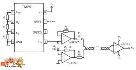
The temperature singal which is exported form TMP01 5-foot is a analog voltage, it will introduce outside interference easily when in industrial site. So it can adopt twisted-pair transmission singal, the circuit is as shown. Firstly, it uses a OP297 to divided U0 into two parts singals, then the singal is transported by twisted-pair, at last, it uses a AMP03 to receive and restore singal in the terminal. Besides amplifying the temperature singal, the differential amplifier which is composed of AMP03 also can reduce the twisted-pair's noise voltage 95dB, after it is restored, it can obtain undistorted signal voltage U0.
(View)
View full Circuit Diagram | Comments | Reading(752)
Steper Motor Driver System Principle Circuit
Published:2011/5/7 20:42:00 Author:Robert | Keyword: Steper Motor, Driver System
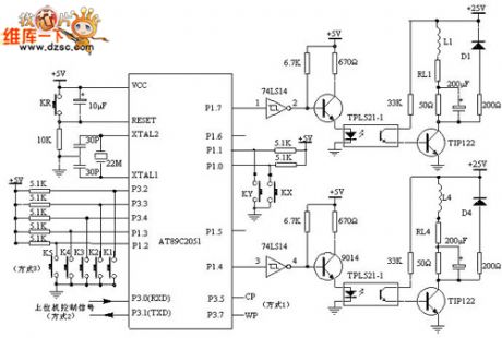
The steper motor driver system principle circuit is shown in the picture below.
The AT89C2051 outputs the control pulses from the P1's P1.4~P1.7 port, then these pulse signals are phase inverted by the 74LS14 to enter 9014, after its amplification these signals then control the photoelectric switch. After optical isolation, the pulse signals' voltage and current are amplified by the power tube TIP122 and then drive the stepper motor every phase windings. It would make the stepper motor have the corotation, reversion, acceleration, deceleration and stop movement with differential pulse signals. L1 shown in the picture is one phase winding of the stepper motor. The AT89C2051 is chosen to use 22MHz crystal. The purpose of using the high-frequency crystal is minimizing the influences on the PC pulse signal cycles by the AT89C2051 in mode 2.
The RL1~RL4 is winding resistance shown picture 1. The 50Ω resistance is a external resistance for current limiting, which is also a component to improve the loop circuit's time constant. D1~D4 are freewheeling diodes, which making the opposing electromotive force produced by motor winding be attenuated through them to protect the power tube TIP122 from damaged.
If the 50Ω external resistance is in parallel with a 200uF capacitor, it would improve the front of the current pulses which are transmitted to the stepper motor to improve the high-frequency performance of the stepper motor.
(View)
View full Circuit Diagram | Comments | Reading(1516)
using RDP-18 pyroelectric infrared control spotlight circuit
Published:2011/5/10 7:22:00 Author: | Keyword: pyroelectric infrared, control, spotlight

(View)
View full Circuit Diagram | Comments | Reading(486)
using P228 pyroelectric infrared control spotlight circuit
Published:2011/5/10 7:21:00 Author: | Keyword: pyroelectric infrared, control, spotlight

(View)
View full Circuit Diagram | Comments | Reading(490)
using HT76108 pyroelectric infrared control spotlight circuit
Published:2011/5/10 7:19:00 Author: | Keyword: pyroelectric infrared, control, spotlight

(View)
View full Circuit Diagram | Comments | Reading(570)
using BH9402 pyroelectric infrared control spotlight circuit
Published:2011/5/10 7:18:00 Author: | Keyword: pyroelectric infrared, control, spotlight

(View)
View full Circuit Diagram | Comments | Reading(459)
using CSl9508 pyroelectric infrared control spotlight circuit
Published:2011/5/10 7:17:00 Author: | Keyword: pyroelectric infrared, control, spotlight

(View)
View full Circuit Diagram | Comments | Reading(434)
using DH-03C pyroelectric infrared control delay spotlight circuit
Published:2011/5/9 9:21:00 Author: | Keyword: pyroelectric infrared , delay, spotlight

(View)
View full Circuit Diagram | Comments | Reading(424)
UCC3918 Hot Swap Control Circuit
Published:2011/5/9 9:08:00 Author:Robert | Keyword: Hot Swap, Control
The UCC3918 Hot Swap Control Circuit is shown below.
(View)
View full Circuit Diagram | Comments | Reading(451)
Current Reducing Protection Application Cirrcuit Composed of WB705
Published:2011/5/6 7:57:00 Author:Robert | Keyword: Current Reducing, Protection, Application


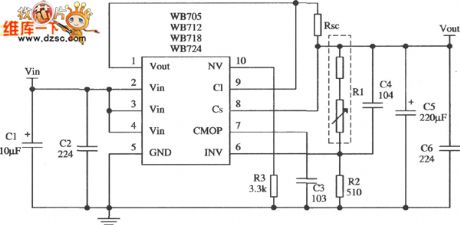
The picture shown below is about the current-reducing protection application cirrcuit with output voltage of 15V and output current of 2A which is composed of WB718 multi-port adjustable positive integrated stabilizer. The input voltage of the circuit in the picture can choose to be 30V~32V. The filter capacitor and vibration-limiting capacitor etc. are the same with those in the application of the current-limiting type. The sample resistance R1 and R2's choice depends on the formula below:The Potentiometer R1 is taken 560Ω and the pull-up resistance is taken 1.2kΩ. The current-limiting resistance is shown in the picture below. In its formula Is is the current value after load is short which is generally taken 1/3ILmax; Vbe, ILmax etc. are the same value with those in the application of current-limiting type. R3's caculation formula is shown in the picture below. In its formula: R10 is the base resistance in the stabilizer internal protection tube which is generally taken 200~250Ω. So These formula's caculation results are approximate. The rest of the circuit is just the same with those in the application circuit of current-limiting type.
(View)
View full Circuit Diagram | Comments | Reading(518)
Remote alarm grating circuit
Published:2011/5/9 9:07:00 Author:Christina | Keyword: Remote alarm, grating
The Remote alarm grating circuit is as shown:
(View)
View full Circuit Diagram | Comments | Reading(486)
human remote sensing fan automatic control circuit
Published:2011/5/9 9:25:00 Author:Christina | Keyword: human remote sensing, fan automatic control

View full Circuit Diagram | Comments | Reading(583)
Application circuit of the op amp
Published:2011/5/9 9:33:00 Author:Christina | Keyword: Application, op amp
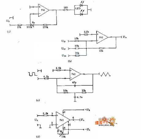
Figure (a) is the polarity monitor with two LEDs, this device can differentiate the polarity of input signal or compare the size of the signal. You can use the potentiometer RP to adjust the sensitivity of the LEDs.
Figure (b) can be used to add the signals of UE1, UE2, UE3.
Figure (c) is the precision integrator circuit, the RC network must match the input signal.
Figure (d) is the comparator circuit.
(View)
View full Circuit Diagram | Comments | Reading(598)
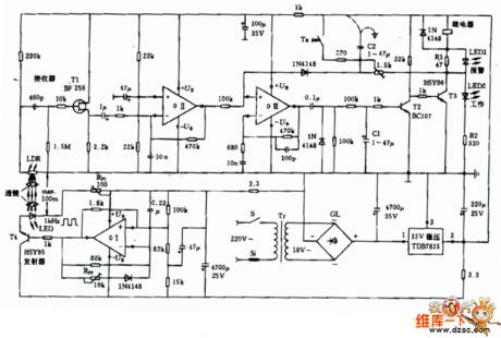
Two-tone doorbell circuit
Published:2011/5/9 8:48:00 Author:Christina | Keyword: Two-tone, doorbell
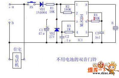
Use the 48V (60V) DC feedback electric current which is provided by the phone feedback line as the working energy of the electronic doorbell is very economical and practical. Now I introduce one kind of two-tone doorbell circuit with out battery. The circuit is as shown, circuit in this figure is the variant of conventional telephone ringing circuit.
a, b are the positive and negative ports of the home telephone line. AN is the normally open doorbell button, when the telephone is in the standby mode, if you press AN, the 48V (or 60V) voltage (which is provided by the PBX) and the DC feedback current will charge capacitor C1 through VD1 and R1, when C1's voltage reaches IC1's start-control voltage, IC1 starts to send out the current of two-tone electronic bell to make the buzzer B sounds, to inform the host when guests are visiting.
When the phone is in using, voltage between a and b can not reaches the IC1's start-control voltage, at this point, even if you press AN, the doorbell button will not work because the R1's value is larger than the telephone's impedance. So if you press AN, there is no effect on the normal call, and also the PBX, but when you use the doorbell, the telephone will be busy. (View)
View full Circuit Diagram | Comments | Reading(2123)
water boiling alarm circuit
Published:2011/5/9 9:56:00 Author:Christina | Keyword: water boiling, alarm circuit
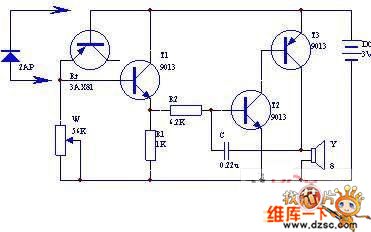
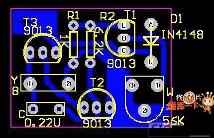
This water boiling alarm circuit is composed of four transistors, the circuit is as shown. The audio oscillator is composed of the transistor T2, T3, the resistor R2 and the capacitor C, the audio signal is output by the speaker.
The switch circuit is composed of the transistor T1, the resistor R1, W and the transistor be node Rt, and it can be used as the audio oscillator control switch.Rt is the temperature sensing element (T1's bias resistor). Usually Rt and T1 are in the reverse cutoff state; when the temperature rises, Rt's reverse resistance gets smaller, the leakage current increases, T1 has some bias to conduct, the audio oscillator starts working and the speaker sounds.
In this figure, transistor T1's magnification needs to be more than 50, T2,T3's magnification needs to be more than 100. The temperature sensor Rt uses the metal shell germanium transistor's be node, such as the 3AX81.etc, also you can use the 2AP-type germanium diode.
(View)
View full Circuit Diagram | Comments | Reading(865)
| Pages:270/312 At 20261262263264265266267268269270271272273274275276277278279280Under 20 |
Circuit Categories
power supply circuit
Amplifier Circuit
Basic Circuit
LED and Light Circuit
Sensor Circuit
Signal Processing
Electrical Equipment Circuit
Control Circuit
Remote Control Circuit
A/D-D/A Converter Circuit
Audio Circuit
Measuring and Test Circuit
Communication Circuit
Computer-Related Circuit
555 Circuit
Automotive Circuit
Repairing Circuit