
Index 269
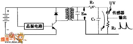
Ultraviolet ray sensor drive circuit diagram
Published:2011/5/11 22:15:00 Author:Nicole | Keyword: Ultraviolet ray, sensor drive
View full Circuit Diagram | Comments | Reading(514)
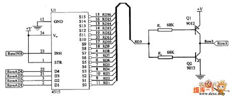
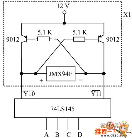
No cross-effect passive OLED drive circuit diagram
Published:2011/5/11 21:43:00 Author:Nicole | Keyword: No cross-effect, passive OLED drive
View full Circuit Diagram | Comments | Reading(774)
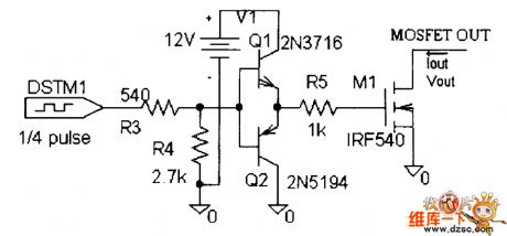
A stepping motor PWM constant current drive circuit diagram
Published:2011/5/11 21:40:00 Author:Nicole | Keyword: stepping motor, PWM, constant current drive

View full Circuit Diagram | Comments | Reading(758)
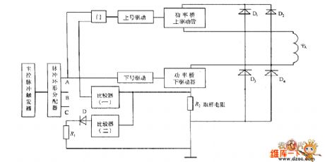
Piezoelectric traveling wave motor drive circuit diagram
Published:2011/5/11 21:39:00 Author:Nicole | Keyword: piezoelectric traveling wave, motor drive
View full Circuit Diagram | Comments | Reading(686)
Stepping motor constant current chopping driver circuit diagram
Published:2011/5/11 21:37:00 Author:Nicole | Keyword: Stepping motor, constant current chopping, driver
View full Circuit Diagram | Comments | Reading(735)
Microcomputer prepayment electric energy meter drive control circuit diagram
Published:2011/5/11 21:35:00 Author:Nicole | Keyword: Microcomputer, prepayment, electric energy meter, drive control
View full Circuit Diagram | Comments | Reading(585)
FAW Jiabao unite electronic system circuit diagram
Published:2011/5/11 22:16:00 Author:Rebekka | Keyword: FAW Jiabao, unite electronic system
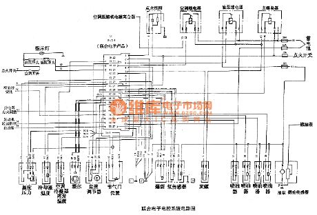
FAW Jiabao unite electronic system circuit diagram is shown as above. (View)
View full Circuit Diagram | Comments | Reading(573)
FAW Jiabao Delphi electronic control system circuit diagram
Published:2011/5/11 22:15:00 Author:Rebekka | Keyword: FAW Jiabao Delphi, Electronic control system
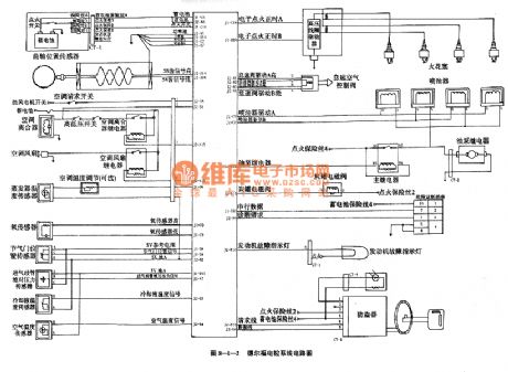
FAW Jiabao Delphi electronic control system circuit diagram is shown as above. (View)
View full Circuit Diagram | Comments | Reading(990)
PQO5RF controllable voltage regulator integrated circuit diagram
Published:2011/5/6 4:23:00 Author:Rebekka | Keyword: Controllable voltage regulator , integrated circuit
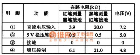
PQO5RF is a controllable voltage regulator integrated circuits. It is widely used in large screen color TV. PQO5RF is a 4 pin single integrated circuit package, the integrated circuit pin functions and data are listed in Table 11.
Table 1 shows pin function and data of PQO5RF integrated circuit.
(View)
View full Circuit Diagram | Comments | Reading(919)
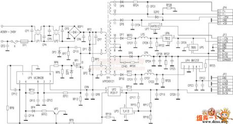
Amoi DVD switching power supply circuit
Published:2011/5/11 6:29:00 Author:Christina | Keyword: Amoi, switching power supply, DVD
View full Circuit Diagram | Comments | Reading(1229)
DC Motor Control Circuit
Published:2011/5/11 7:42:00 Author:Robert | Keyword: DC, Motor, Control
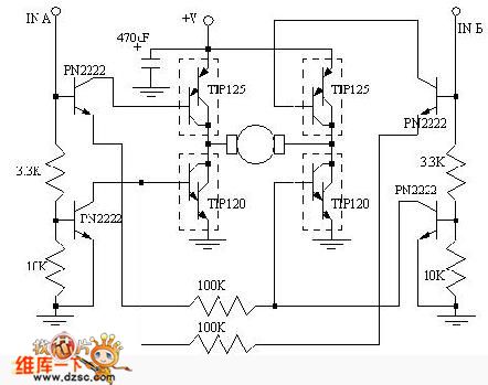
Aboutthe DC motor control problem, This circuit is hoped to help those people who have the actual needs. This circuit's corotation, rollback, slowing and stopping functions can be controlled by the connected MCU.
(View)
View full Circuit Diagram | Comments | Reading(2108)
Gateball competition timer circuit diagram
Published:2011/5/11 3:51:00 Author:Rebekka | Keyword: Gateball competition timer
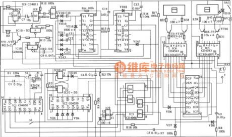
The diagram of gateball competition timer circuit. (View)
View full Circuit Diagram | Comments | Reading(601)
Operational amplifier differential-mode voltage puncture input protection measures circuit diagram 2
Published:2011/5/11 3:48:00 Author:Rebekka | Keyword: protection measures , Operational amplifier, puncture input
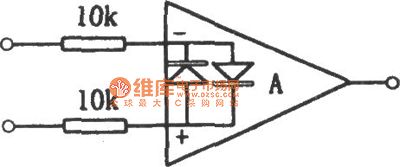
The protection circuit of internal protective measures integrated chip (such as the 741 series and the type of integrated FET input op amp) is shown as above. Its limiting current resistor can be up to 10kΩ.
(View)
View full Circuit Diagram | Comments | Reading(706)
Power capacitor compensation protection circuit diagram
Published:2011/5/11 4:25:00 Author:Rebekka | Keyword: Power capacitor compensation protection
The circuit is shown in the figure. It is used in power supply circuit. It can cut off the power when it is overvoltage or power-off phase. So that the power capacitor can be protected. (View)
View full Circuit Diagram | Comments | Reading(683)
Overheat protection system circuit composed of MIC2951
Published:2011/5/11 4:36:00 Author:Rebekka | Keyword: Overheat protection system
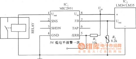
The figure shows the overheat protection system circuit composed of MIC2951. The temperature threshold value of circuit is set by the adjustment R2. (View)
View full Circuit Diagram | Comments | Reading(805)
The typical application circuit of pulse width modulation power controller
Published:2011/5/11 2:06:00 Author:Rebekka | Keyword: pulse width modulation power controller
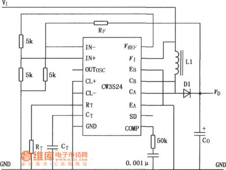
Here is the diagram ofCW1524 CW2524 CW3524 the pulse width modulation power controller typical application circuit. (View)
View full Circuit Diagram | Comments | Reading(615)
Kettle automatic alarm circuit
Published:2011/5/8 19:57:00 Author:Christina | Keyword: Kettle, automatic alarm
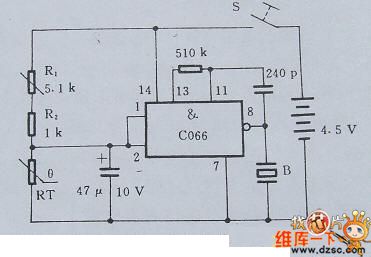
When you boil water by the home gas stove, it often spills off the flame by the boiling water, and this leads to gas leak. This is a waste of energy and would cause serious accidents. Use the Kettle automatic alarm which is made by the PTC thermistor, you can prevent the accidents.
1 circuit principle
The core of this kettle automatic alarm circuit is composed of the NAND IC block and the PTC thermistor, the circuit principle is as shown in figure 1. Before the water temperature meets the default value, RT's resistance is small, IC's input voltage is lower than the threshold voltage, B will not alarm. When the water temperature meets the boiling point, RT's resistance increase rapidly and higher than the threshold voltage, after 30 seconds, IC outputs the voice signal and B issues the alarm.
Figure 1. Kettle automatic alarm circuit
2 Select the main components
The Kettle automatic alarm circuit's RT temperature probe uses the PTC thermistor, the room temperature resistance is ≤500Ω, the standard resistance - temperature characteristic curve is as shown in figure 2.8.2. Buzzer B uses the Ф27mm.
Figure 2. The standard resistance - temperature characteristic curve
3 Installation and Commissioning
When you use it, put the temperature sensor end into the kettle, the alarm installed in the place where is easy to hear the alarm sound, and notic the moisture. (View)
View full Circuit Diagram | Comments | Reading(1624)
SN75480 High Voltage Seven Segments Decoder/Cathode Drive Circuit
Published:2011/5/11 0:01:00 Author:chopper | Keyword: High Voltage Seven Segments Decoder, Cathode drive
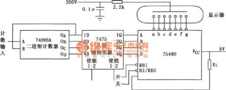
As shown in figure is ahexadecimal SN75480 drive gas discharge display circuit.
(View)
View full Circuit Diagram | Comments | Reading(1045)
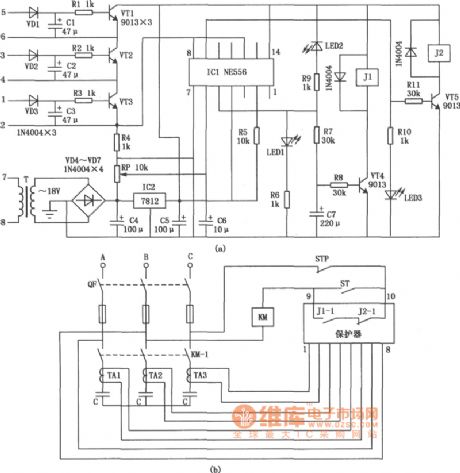
Straw And Feed Muller Control Circuit
Published:2011/5/6 3:07:00 Author:Robert | Keyword: Straw, Feed, Muller
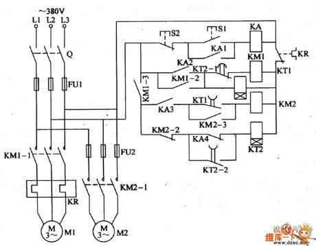
For the straw feed muller used in the countryside to process the corn, straw and grass and other animal feeding stuffs, some people use two electric motor (feeding motor and cropping motor) as the power to complete the crushing job for straw and feed. To avoid the cropping motor's rotor locking, it is required that the cropping motor should run firstly for a period time, and then lets the feeding motor run. The straw feed muller control circuit introduced by this model can control the two motors' woking status automatically.The circuit's working principle is shown below.This straw feed muller control circuit is made up by knife switch Q, fuse FU1, FU2, thermal relay, AC connector KM1, KM2, time relay KT1, KT2, middle relay KA and control button S1, S2 and so on, which is shown in the picture.The cropping motor M1's main circuit is made up by Q, FU1, KM1's normally open main contactor KM1-1, KR thermal elements.The feeding motor M2's main circuit is made up by Q, FU1, FU2 and KM2's normally open main contactor KM2-1.The control circuit is made up by start button S1, stop button S2, KA, KM1, KM2, KT1, KT2 and other control contactors. (View)
View full Circuit Diagram | Comments | Reading(993)
Crops Automatical Frost Protection Control Circuit
Published:2011/5/11 1:24:00 Author:Robert | Keyword: Crops, Frost Protection, Control
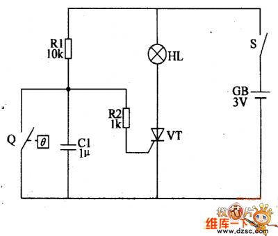
The circuit's working principle is shown below.This crops automatical frost protection control circuit is made up by electrical-contact mercury thermometers Q, control circuit and ignition component and other components which is shown in the picture below.The difference between the electrical-contact mercury thermometers and general mercury thermometers is that this kind thermometers's mercury cavity has been inserted two platinum button electrodes. One is inserted in the upside of the thermometers mercury cavity as a contactor electrode, and the other is inserted in the temperature scale line which need to be controlled as a control electrode. When using this device it should adjust the monitoring and control temperature (combustion smoke temperature) to be +1℃.The control circuit is made up by thyristor VT, resistance R1, R2 and capacitor C.The ignition component is made up by 2.5V little lamp HL and gunpowder etc. First to extract two lines from the two electrode of the little lamp HL, and also use fine sandpaper or fine grinding wheel to rub a small hole in the top of HL glass ball. Then insert some gunpowder from the small hole into the grass ball. Using a appropriate size plastic membrane to wrap up the small lamp HT, and there are about 20g gunpowder in it as the detonator for smoke material. When using this device, accumulate the smoke material on the detonator, and put some soil on the smake material to prevent the burning of smoke material starter.
(View)
View full Circuit Diagram | Comments | Reading(694)
| Pages:269/312 At 20261262263264265266267268269270271272273274275276277278279280Under 20 |
Circuit Categories
power supply circuit
Amplifier Circuit
Basic Circuit
LED and Light Circuit
Sensor Circuit
Signal Processing
Electrical Equipment Circuit
Control Circuit
Remote Control Circuit
A/D-D/A Converter Circuit
Audio Circuit
Measuring and Test Circuit
Communication Circuit
Computer-Related Circuit
555 Circuit
Automotive Circuit
Repairing Circuit