
Index 286
Light switch circuit with luminous indication
Published:2011/4/19 6:42:00 Author:Nicole | Keyword: Light switch, luminous indication
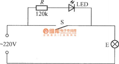
The light switch circuit with luminous indication is as shown, when the switch S is turned on , 220V AC power supply is pressure released and current limited by resistance R, then it is added to the two sides of LED with bulb E, making LED conduction and lighting, it is convenient to find the switch at night. The current flows E is tiny, it is only about 2mA, this can be considered there is no power consumption, the light is off too. To close S, bulb E can work normally, but LED turns off. To open S, LED does not light, if the filament of bulb E is not burned out, then it must be power failure. (View)
View full Circuit Diagram | Comments | Reading(1650)
Intermittent timer circuit composed of two RS6445C long time timing integrated circuit
Published:2011/4/19 4:44:00 Author:Nicole | Keyword: timer, long time timing
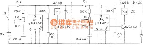
This circuit can control equipments intermittent work. In figure, 4, 5 feet are grouding, the preset level are all low level L, potentiometer RP1 and RP2 is used to adjust the working time and stopping time, both can continuous adjust in 0.5~24 hours. If it is needed to decrease the timing time, you can increase the potentiometer resistance. If it is divided into two according to the dashed line in figure, then it will to be two separate timers. (View)
View full Circuit Diagram | Comments | Reading(824)
Delay light circuit with time base circuit
Published:2011/4/20 23:01:00 Author:Nicole | Keyword: Delay light, time base
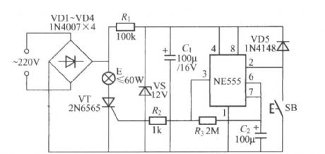
The figure is as shown, it is a delay light circuit with time base circuit, the delay time is decided by the charging time parameters of R3、C2, the data is about 4min. (View)
View full Circuit Diagram | Comments | Reading(514)
Delay light circuit with time base circuit(3)
Published:2011/4/20 23:51:00 Author:Nicole | Keyword: Delay light, time base
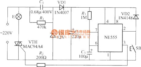
The figure is as shown, the delay time is decided by the values of R3、C3, the data is as shown, the lighting time is about 150s. (View)
View full Circuit Diagram | Comments | Reading(683)
Timing trigger SCP circuit composed of SGZ35 time control integrated circuit
Published:2011/4/19 4:42:00 Author:Nicole | Keyword: Timing trigger, SCP, time control
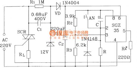
In figure, there are two kinds of timing, delay control circiuts. Setting the value of R, C to make the timing or delay time change between few microseconds and few hours. (View)
View full Circuit Diagram | Comments | Reading(691)
SR63 multi-function festival color lamp with firecrackers sound contorl circuit
Published:2011/4/18 10:07:00 Author:Nicole | Keyword: festival color lamp, firecrackers sound
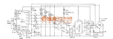
SR63 is a large scale CMOS festival color lamp control special integrated circuit, it has four ways output drive singal, it has eight kinds light changing modes, three of them are chase modes, three of them are dimming modes, one is automatic mixed mode and the other is function lock mode. The color lamp control circuit with the core of SR63 device is as shown. The circuit consists of SR63 color lamp drive circuit, firecrackers sound contorl, audio frequency power amplifier circuit and AC depressurization rectifier circuit. (View)
View full Circuit Diagram | Comments | Reading(504)
M668 touch stepping dimming light circuit
Published:2011/4/19 6:54:00 Author:Nicole | Keyword: stepping dimming light
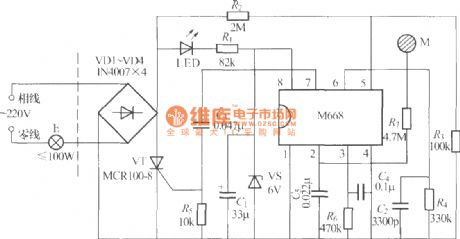
The figure is as shown, it is a touch stepping dimming light with M668 IC, the feature of it is its dimmer uses two-wire system connection, there are only two outgoing lines outward, so it canreplace the ordinary light switch, changing the ordinary light into touch four grades dimming light. (View)
View full Circuit Diagram | Comments | Reading(984)
Automatic gas circulatory stove temperature control circuit diagram
Published:2011/4/14 2:22:00 Author:Ecco | Keyword: Automatic , gas circulatory stove, temperature control
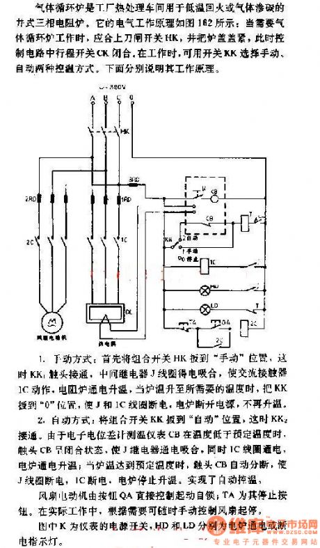
1. Manual method: First, to pull combination switch HK to manual position, then the contacts of KK1 are connected, the relay J coil is energized pull, the AC contactor IC takes action, resistance furnaceis heating, when the temperature rose to the required temperature, to pull KK to 0 position, so that J and JC coil lose power, electrical furnace loses the power, and it won's rise the temperature again.
2. Automatic way: To pull combination switch HK to the automatic position, then the contacts of KK2 are connected, since the digital potentiometer thermometer CB is below the predetermined temperature, contact CB is closed, so that J is energized pull, and IC coils get electric power to heat up the electrical furnace. When the temperature reaches a predetermined temperature, contact CB automatic breaking, so that J coil and IC breaking, electrical furnace stops heating, to realize automatic temperature control.
The K in the chart is the power switch of meter. HD and LD are the energizing and breaking indications.
(View)
View full Circuit Diagram | Comments | Reading(620)
Photoelectric isolation circuit between TTL circuit and relay circuit
Published:2011/4/20 8:44:00 Author:Nicole | Keyword: photoelectric isolation, TTL, relay
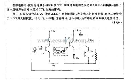
In this circuit, using a photoelectric coupler can reach 100GΩ isolation between TTL and relay circuit, it avoids relay noise and peak voltage influencing TTL circuit.
When the TTL input singal is high, Q1 turns on, there is no current in LED, and there is no light incident on detecor, photoelectric diode is in 5GΩ maximum impedance value. So Q2 is nonconductive, then Q3 is nonconductive too, and there is no current in relay coil. (View)
View full Circuit Diagram | Comments | Reading(1493)
M62253FP charge controllor
Published:2011/4/20 9:01:00 Author:Nicole | Keyword: charge controller
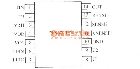
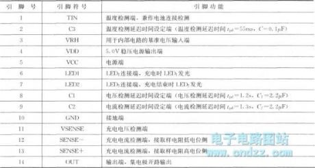
M62253FP is produced by Janpan Mitsubishi Electric C.Ltd, it is used specifically for the charge controllor of lithium ion battery. The pin arrangement diagram is as below:
(View)
View full Circuit Diagram | Comments | Reading(429)
Vegetable greenhouse humidity detection automatic ventilating with cricket chirped circuit
Published:2011/4/20 4:31:00 Author:Nicole | Keyword: vegetable greenhouse, humidity detection, automatic ventilating, cricket chirped

The circuit is as shown. It consists of temperature detection circuit, schmidt trigger circuit, SCR control ventilating circuit, voice phonation circuit and AC depressurization rectifier circuit. It can detect the high humidity environment, when the relative humidity beyond the set value, the circuit will send out cricket chirp, and start discharge fan to operate, ventilate. (View)
View full Circuit Diagram | Comments | Reading(787)
SCR phase shifting control circuit with small conduction angle
Published:2011/4/18 9:51:00 Author:Nicole | Keyword: SCR, phase shifting control, conduction angle
This circuit is a single phase half wave rectification citcuit,which can drive load RL0. The control angle changes between 2°~60° through adjusting 50kΩ potentiometer. The resistance R is decided by the using SCR gate parameter, and the SCR parameter depends on load. If the load resistance is 135Ω, then the output power is 135Ω, SCR peak current is 2.3A, the resistance should be 390Ω. (View)
View full Circuit Diagram | Comments | Reading(543)
4h Timing circuit composed of 556
Published:2011/4/14 3:42:00 Author:Ecco | Keyword: 4h , Timing circuit
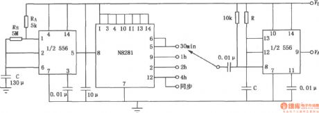
The figure shows 4h timing circuit which is composed of 556 dual time base circuit. To access N8281 divider network in the middle of 556 dual time base circuit, it will get a long time delay without large volume of capacitors. The first l / 2 (556) works in the way of oscillator, the period is l / f. It will produce the signal output in a N / f cycle to trigger the other half 1 / 2 (556) to add the output of oscillator to N divider network. It decides the total delay produced by the dividerto connect the divider to ⑧ pin of the second 1 / 2 (556) input terminal. Delay time is divided in 4 blocks of 30min, 1h, 2h, 4h. If connecting N8281 crossover in series additionally , the total amount of delay can be increased to days or even weeks.
(View)
View full Circuit Diagram | Comments | Reading(1893)
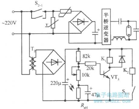
Automatic opening/closing circuit (Rph is photoresistance)
Published:2011/4/20 6:34:00 Author:May | Keyword: Automatic opening/closing, Rph, photoresistance
View full Circuit Diagram | Comments | Reading(650)
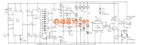
VH5162 festival color lamp with "good luck" voice control circuit
Published:2011/4/20 3:34:00 Author:Nicole | Keyword: festival color lamp, voice
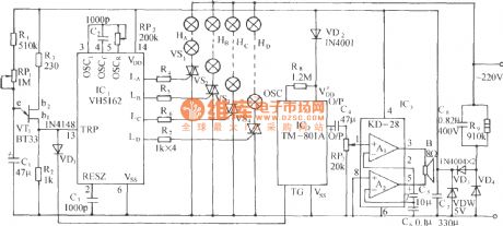
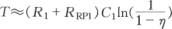
VH5162 is a CMOS festival color lamp control circuit, it has four ways color lamp drive output, eight work modes. The figure of festival color lamp with good luck voice control circuit is as shown. The change of work mode adopts clock sequence control way, the unijunction tube relaxation oscillator generator provides trigger clock. VT1(BT33) and R1,RP1,C1 and R2 form the low frequency relaxation oscillator, its oscillation period is:
The η is unijunction tube attenuation ratio, generally η=0.35~0.55. (View)
View full Circuit Diagram | Comments | Reading(470)
The precise timing circuit for correcting capacitor tolerance
Published:2011/4/20 3:32:00 Author:Ecco | Keyword: precise , timing circuit , correcting , capacitor tolerance
View full Circuit Diagram | Comments | Reading(540)
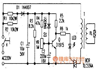
TLC336A bi-directional controllable thyristor application circuit
Published:2011/4/20 3:20:00 Author:Jessie | Keyword: bi-directional, thyristor, controllable, application
View full Circuit Diagram | Comments | Reading(1794)
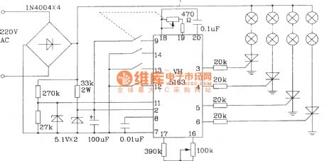
Typical application circuit of VH5163 color lamp control integrated circuit
Published:2011/4/20 3:22:00 Author:Nicole | Keyword: color lamp
View full Circuit Diagram | Comments | Reading(437)
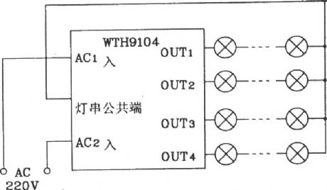
TWH9104 festival multi patterns flashing color lamp with "all the best" voice control circuit
Published:2011/4/20 3:17:00 Author:Nicole | Keyword: flashing color lamp, voice control
The circuit is as shown, it adopts TWH9104 color lamp control circuit as the core to form this circuit, the color lamp patterns are automatical selected by the pulse count or the distribution circuit according to time sequence and level grouping, that is programing and assembling to the different levels of pattern selection control terminal S0, S1, DIM, to achieve the automatic retread and flash change of the color lamp patterns. (View)
View full Circuit Diagram | Comments | Reading(515)
Application circuit of TWH9104 new type color lamp control integrated circuit
Published:2011/4/20 3:00:00 Author:Nicole | Keyword: color lamp,
In figure, the rectifier diode and SCR should use component with 200V withstand voltage. When the load power is more than 100W, according to the real power to change the diode and SCR. (View)
View full Circuit Diagram | Comments | Reading(508)
| Pages:286/312 At 20281282283284285286287288289290291292293294295296297298299300Under 20 |
Circuit Categories
power supply circuit
Amplifier Circuit
Basic Circuit
LED and Light Circuit
Sensor Circuit
Signal Processing
Electrical Equipment Circuit
Control Circuit
Remote Control Circuit
A/D-D/A Converter Circuit
Audio Circuit
Measuring and Test Circuit
Communication Circuit
Computer-Related Circuit
555 Circuit
Automotive Circuit
Repairing Circuit