
Index 85
Electronic decorative peacock flaunting circuit of CD4017,NE555
Published:2011/7/26 6:06:00 Author:chopper | Keyword: Electronic, decorative, peacock flaunting
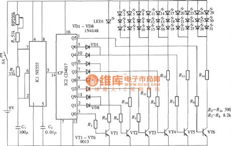
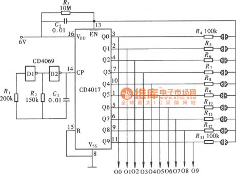
Electronic decorative peacock flaunting includes 10-group light-emitting diodes,each LED contains multiple light-emitting diodes, and these LEDs are installed on the tail of the peacock in.And under the drive of the light-driven circuit,these LEDs shine circularly and radially by the fan shape,which is like the peacock flaunting,and itis shown as picture. It consists of LED drive circuit, drive pulse oscillator and LEDs. (View)
View full Circuit Diagram | Comments | Reading(3838)
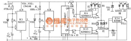
electronic all birds paying homage to the phoenix NE555,CD4017 circuit
Published:2011/8/25 20:14:00 Author:chopper | Keyword: electronic, all birds paying homage to the phoenix
View full Circuit Diagram | Comments | Reading(1310)
Electronic birthday candle circuit
Published:2011/7/26 5:35:00 Author:chopper | Keyword: Electronic, birthday candle
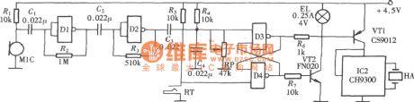
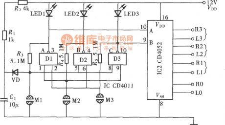
Electronic birthday candle includes a candle and a Happy Birthday Song. It imitates the shape of traditional birthday candles and adopts the operation mode like lighting and blowing candle, it is very interesting, the circuit is shown as picture. It consists of a 412 input end and nand-gate CD4011,and D3, D4 form the trigger RS, it uses two output states of trigger to control the lighting, blowing as well as the play and stop of the candle.
(View)
View full Circuit Diagram | Comments | Reading(1831)
touch type voltage regulator circuit of NE555,CD4017
Published:2011/7/25 2:45:00 Author:chopper | Keyword: touch type, voltage regulator
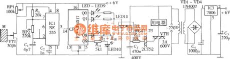
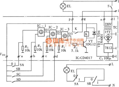
The picture shows the touch type voltage regulator,which can adjust the photoconductive resistance mainly by changing the brightness of LED,and then adjust the conduction degree of the bidirectional thyristor through triggering the diode trigger circuit, and ultimately achieve the purpose of the voltage regulation.The circuit is shown as picture.It consists of bidirectional thyristor trigger circuit, LED brightness adjustment circuit as well as regulating impulse generation and control circuit.
(View)
View full Circuit Diagram | Comments | Reading(1556)
LM555 broad dynamic pulse width modulator circuit
Published:2011/7/24 3:36:00 Author:chopper | Keyword: broad dynamic, pulse width, modulator
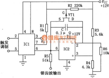
Broad dynamic pulse width modulator is mainly formed by the integrated timer circuit and integral circuit. As a result of op-amp, the temperature stability is good, linear dynamic range is wide, and the narrowest output pulse is 2μs, the widest pulse is 6ms,the ratio of wide, narrow pulse can reach 300:1. With the change of the modulativon input signal, the corresponding change of output pulse width will happen, resulting in the effect of pulse-width, and it can also output a saw-tooth-wave voltage signal at the same time.
(View)
View full Circuit Diagram | Comments | Reading(1679)
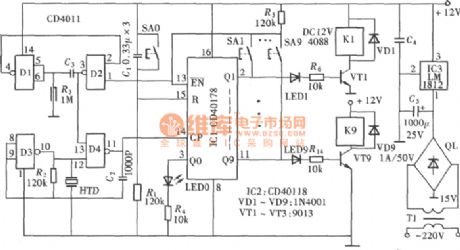
ten-gear interlock switch(CD4011,LM1812) circuit with audible and visual indication
Published:2011/7/23 2:25:00 Author:chopper | Keyword: ten-gear, interlock switch, audible and visual indication
View full Circuit Diagram | Comments | Reading(1645)
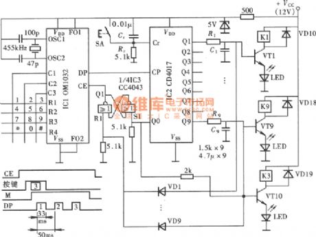
piano key type electronic switch OM1032,CD4043,CD4017 circuit
Published:2011/8/25 20:13:00 Author:chopper | Keyword: piano key, electronic switch
View full Circuit Diagram | Comments | Reading(3338)
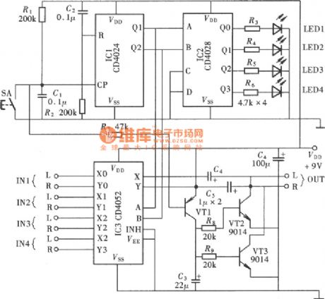
quadruple sound source input switching CD4024,CD4052 circuit
Published:2011/8/25 20:13:00 Author:chopper | Keyword: quadruple, sound source, input switching
View full Circuit Diagram | Comments | Reading(8862)
CD4520 digital coded lock circuit
Published:2011/7/25 2:49:00 Author:chopper | Keyword: digital, coded lock
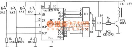
Figure shows the general-purpose digital coded lock circuit formed by the CMOS digital integrated circuit, which is characterized by a wide supply voltage range, low power consumption, anti-jamming performance, fewer external components.There are 256 password combinations, and it is of pseudo-code switch, and has a good security feature, the circuit is shown as figure.The coded lock circuit consists of a dual-binary synchronous add counter CD4520,and there are two binary counters of same structure in the circuit.
(View)
View full Circuit Diagram | Comments | Reading(2135)
digital coded lock circuit with CD4520
Published:2011/7/22 3:29:00 Author:chopper | Keyword: digital, coded lock
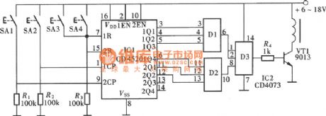
Figure shows the general-purpose digital coded lock circuit formed by the CMOS digital integrated circuit, which is characterized by a wide supply voltage range, low power consumption, anti-jamming performance, fewer external components.There are 256 password combinations, and it is of pseudo-code switch, and has a good security feature, the circuit is shown as figure.The coded lock circuit consists of a dual-binary synchronous add counter CD4520,and there are twobinary counters of same structure in the circuit.
(View)
View full Circuit Diagram | Comments | Reading(3129)
Grid Electrode Isolated Driving Circuit For Half-Bridge Circuit
Published:2011/8/23 23:39:00 Author:Robert | Keyword: Grid, Electrode, Isolated, Driving, Half-Bridge
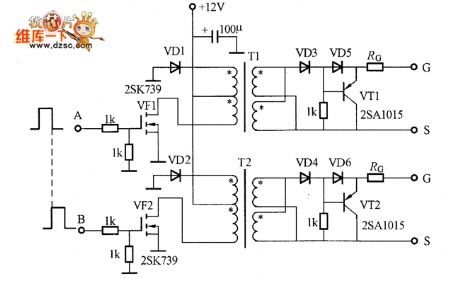
The picture shows the grid electrode isolated driving circuit for half-bridge circuit. The input signal A and B are the signals provided by the switching power integrated controller. And when they are added on the transformer, the waveform's duty cycle would be below 50%. The pulse transformer T1 and T2's each winding is separated. Its primary side has two series windings. Its secondary side has two parallel windings. For reducing the VD3~VD6's positive voltage drop, it should use the schottky diode. But if it uses the general diode, that would also be OK. The driving circuit's output port is connected to the driving power MOSFET's grid electrode (G) and source electrode (S). (View)
View full Circuit Diagram | Comments | Reading(874)
four-way electronic change-over switch circuit with CD40157,CD4066
Published:2011/7/22 3:22:00 Author:chopper | Keyword: four-way, electronic, change-over switch
View full Circuit Diagram | Comments | Reading(8210)
touch type three-way audio source change-over switch circuit with CD4052,CD4011
Published:2011/7/22 3:30:00 Author:chopper | Keyword: touch type, three-way, audio source, change-over switch
View full Circuit Diagram | Comments | Reading(6841)
touch type ten-gear interlock switch controller circuit with CD4069,CD4017
Published:2011/7/22 3:09:00 Author:chopper | Keyword: touch type, ten-gear, interlock switch, controller circuit
View full Circuit Diagram | Comments | Reading(1370)
Single-load multi-site switch control circuit formed by CD4017
Published:2011/7/23 2:30:00 Author:chopper | Keyword: Single-load, multi-site, switch control
View full Circuit Diagram | Comments | Reading(819)
Ambulatory Illuminations Program Controller Composed of SN74LS175
Published:2011/8/14 7:09:00 Author:Sue | Keyword: Ambulatory Illuminations, Program Controller
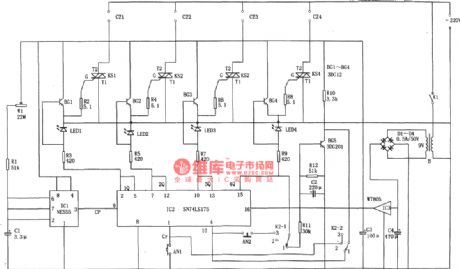
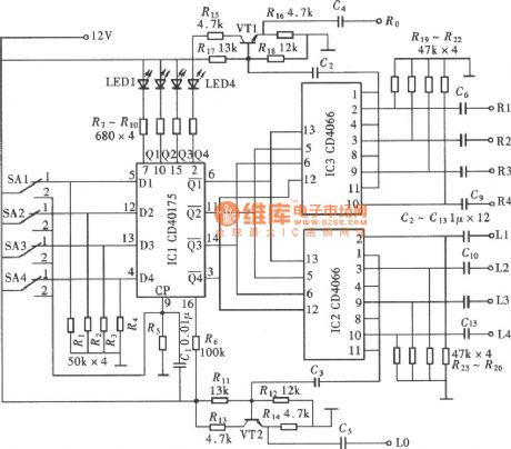
The picture shows the ambulatory illuminations program controller circuit. The program controller consists of pulse generator, logic circuit, silicon control circuit, voltage reduction and rectification circuit. (View)
View full Circuit Diagram | Comments | Reading(949)
Furnace temperature control circuit composed of the AD590
Published:2011/8/23 22:27:00 Author: | Keyword: Furnace, temperature control
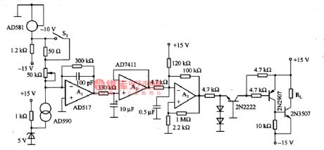
The furnace temperature control circuit which is composed of the AD590 is as shown in the figure. In this circuit, the output current of AD590 is compared with the benchmark current at the reverse phase input port of the Al, this current is decided by the -lOV stable voltage of the high performance voltage-regulator tube AD581; A2 is the filter; A3 is the addition calculator, it amplifies the error signal and adjusts the pulse width drive heater RL according to the temperature value. In order to get the most stable dynamic characteristics, we use the silicon grease to paste the AD590 on the heater RL. Due to the output current sensor AD590 is proportional to the temperature, we can adjust the film resistance of the chip, when the temperature is 298·2K(25℃), the output current is 298·2μA. So we can control the temperature of the furnace.
(View)
View full Circuit Diagram | Comments | Reading(1503)
Temperature detection circuit composed of the diode temperature sensor
Published:2011/8/23 22:29:00 Author: | Keyword: Temperature detection, diode, temperature sensor
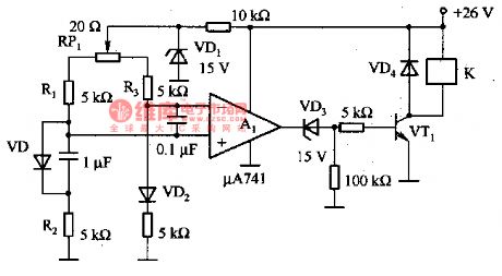
The temperature detection circuit which is composed of the diode temperature sensor is as shown in the figure. In this circuit, the VD is used as the temperature sensor, the VD2 is the temperature compensation diode. The bridge type circuit is composed of the VD, VD2, R1, R2, R3 and RP1, the compensation current of the RP1 fixed diode is about 3uA. Every time when the temperature changes for 1℃, the bridge circuit outputs the 2mV voltage, this voltage is amplified by A1 and encourages the VT1 through VD3, and it drives the relay through VT1.
(View)
View full Circuit Diagram | Comments | Reading(3353)
Rock Illuminations Controller Composed of NE555
Published:2011/8/18 6:18:00 Author: | Keyword: Rock Illuminations, Controller
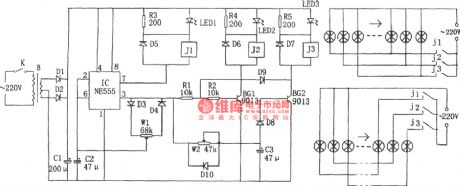
The picture shows the rock illuminations control circuit. The controller consists of voltage reduction and rectification circuit, 555 multivibrator, illuminations control circuit.
For the multivibrator which is composed of 555 and D4,D3,W1,C2, by adjusting W1, the circuit's charging and discharging time constant can be changed which will make the alternating square wave's duty ratio 2:1. When IC(555)'s pin 3 output low level, the inside corresponding discharging tube's discharging function will make pin 7 have low level which will illuminated LED1 and relay J2 will be connected. Then the first group of illuminations will be turned on by the control. (View)
View full Circuit Diagram | Comments | Reading(651)
The solar energy water heater temperature control circuit composed of the thermistor
Published:2011/8/23 22:29:00 Author: | Keyword: solar energy, water heater, temperature control, thermistor
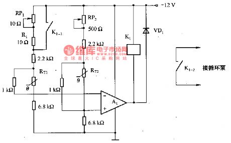
The solar energy water heater temperature control circuit which is composed of the thermistor is as shown in the figure. In this circuit, the thermistor RT1 detects the temperature of the water in the collector, RT2 detects the temperature of the water in the storage device. The temperature changes into the corresponding voltage through the thermistor, and this voltage adds to the input port of the comparator Aa, the output comparison result of A1 controls the circulation pump through the relay K1. The resistance value of the (R(RPl)+Rl) decides the action of the pump, in the actual situation, the resistance value is about 12-18Ω. For example, when the resistance value of (R(RPl)十Rl) is 13Ω, the water temperature of the storage device is 30℃.
(View)
View full Circuit Diagram | Comments | Reading(2755)
| Pages:85/312 At 2081828384858687888990919293949596979899100Under 20 |
Circuit Categories
power supply circuit
Amplifier Circuit
Basic Circuit
LED and Light Circuit
Sensor Circuit
Signal Processing
Electrical Equipment Circuit
Control Circuit
Remote Control Circuit
A/D-D/A Converter Circuit
Audio Circuit
Measuring and Test Circuit
Communication Circuit
Computer-Related Circuit
555 Circuit
Automotive Circuit
Repairing Circuit