
Index 88
PWM Signal Generating Circuit
Published:2011/8/17 10:00:00 Author: | Keyword: PWM, Signal, Generating

The switching power separate excitation control method has pulse width modulation (PWM) and pulse frequency modulation (PFM). And the most cases use the PWM method. So here it would introduce the PWM control principle. The picture shows the PWM signal generating circuit diagram and working waveform. Its working process is following. By detecting the controlled voltage Uo it could get the feedback voltage Ur and then add it to the in-phase port of the amplifier A1. The fixed referenced voltage Uo is added to the out-phase port of A1. After the amplification of A1, the DC error voltage Ue is added to the out-phase port of amplifier A2. And the sawtooth signal Usa, which is generated from the fixed frequency oscillator, is added to the in-phase port of A2. (View)
View full Circuit Diagram | Comments | Reading(1174)
Output Voltage Adjustable Circuit
Published:2011/8/18 2:44:00 Author: | Keyword: Output, Voltage, Adjustable
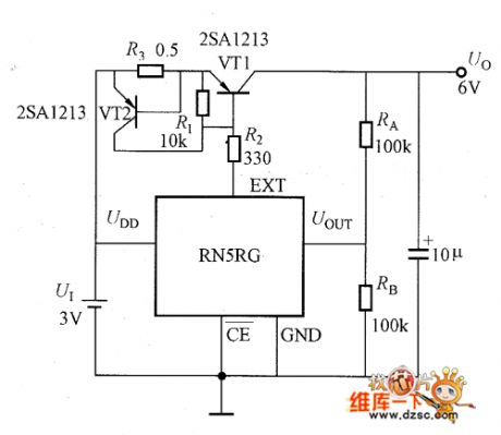
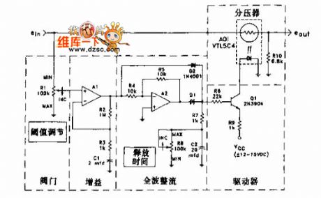
The picture shows the output voltage adjustable circuit, and it also has the over-current protection circuit. The purpose of the EXT port's current limiting circuit is to protect the integrated voltage regulator. It should consider the external connecting transistor and FE's discreteness and the maximum output current, so then it could choose the R2's resistance value. For assuring the current limiting, it is connected the R3 and VT2 whose current limiting value is 0.7V/R3. The UOUT's external connected resistance RA and RB could be used to adjust the output voltage. Because the UOUT port's internal chip has connected to the high-impedance resistance (10MΩ) for detecting and the accelerated capacitance. So even the RA and RB use the hundreds KΩ resistance it would not generate the error. So this could design the low-current-consumption adjustable voltage regulator power. (View)
View full Circuit Diagram | Comments | Reading(846)
The typical high-voltage flashlight circuit
Published:2011/8/18 8:09:00 Author: | Keyword: high-voltage flashlight
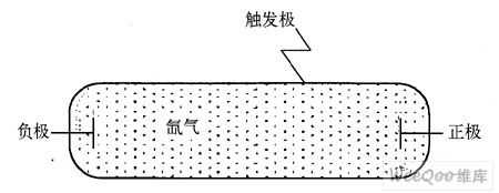
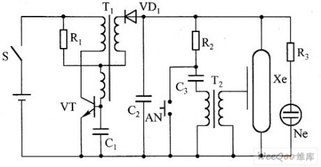
1. The high-voltage flashlight circuit The high-voltage flashlight generate high voltage through the oscillating circuit and booster transformer, and the energy is stored by the large volume storage, which releases and inducts high voltage transiently, so the inert gases are triggered and emitting the pulse light, which is how the high transient power is got. In figure 1 is the prototype of a flashlight, which consists of a glass cover full of xenon, both the negative and positive are dipped in the xenon, but the trigger pole is connected with the surface of the light without dipping in the xenon.
(View)
View full Circuit Diagram | Comments | Reading(982)
Typical application circuit of HFC55 audio control IC
Published:2011/8/8 20:43:00 Author:Ecco | Keyword: Typical application circuit , audio control IC
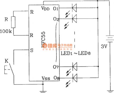
This start-stop control end S of the device is carried by high level, the external end is connected to a pairof groundswitch K. Each time to press it, the circuit can complete the start or stop conversion.
(View)
View full Circuit Diagram | Comments | Reading(672)
CD71017 multi-function programmable lantern control circuit with sound waves
Published:2011/8/8 20:35:00 Author:Ecco | Keyword: multi-function programmable , lantern control , sound waves
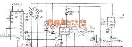
CD71017 is a CMOS programmable flash IC, which has seven road lights control output, strong programmable function, and there are 14 kinds of lights flash pattern. Figure shows the multi-functional programmable controll IC with sound wave which is made by it. It includes the lights control circuit, power amplifier and sound waves and the buck rectifier circuit.
(View)
View full Circuit Diagram | Comments | Reading(755)
Hoist automatically limiting controller circuit diagram
Published:2011/8/11 1:32:00 Author:Ecco | Keyword: Hoist , automatically limiting controller
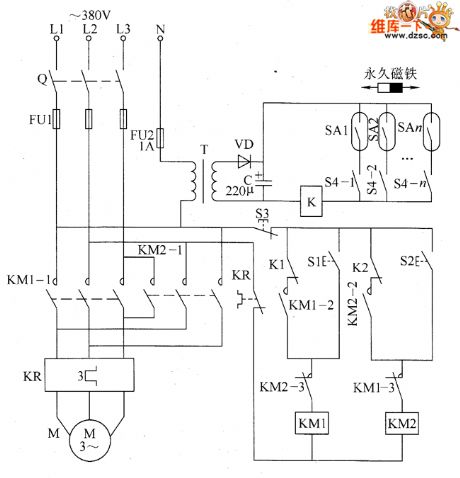
The hoist automatically limiting controller circuit is composed of the knife switch Q, fuses FU1 and FU2, thermal relay KR, relay K, AC contactors KMI and KM2, increasing control button S1, dropping control button S2, stop button S3, key self-locking control switch S4 (S4-1 ~ S4-n), reeds SA1 ~ SAn, power transformer T, rectifier diode VD and filter capacitor C, and it is shown as the chart. VD selects the 1N4007 silicon rectifier diode. C selects the aluminum electrolytic capacitor with voltage in 25V.
(View)
View full Circuit Diagram | Comments | Reading(3212)
Dense rock pile driver automatic controller circuit diagram
Published:2011/8/15 2:00:00 Author:Ecco | Keyword: Dense rock, pile driver , automatic controller
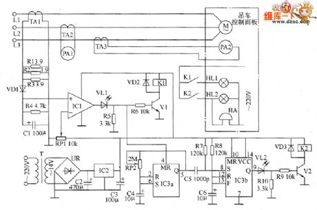
The dense rock pile driver automatic controller circuit is composed of the power supply circuit, current detection and indication circuit and control warning circuit, and it is shown as the chart. Power supply circuit is composed of the power transformer T, bridge rectifier UR, filter capacitors C2, C3, and three-terminal voltage regulator integrated circuit IC2. Current detection and indication circuit is composed of the current transformers TA1 ~ TA3, resistors R1 ~ R4, potentiometer RP1, diode VD1, capacitor C1, current meters PA1, PA2 and the operational amplifier integrated circuit IC1. M ~ R10 select the 1/4W metal film resistors. VD1 ~ VD3 use the 1N4001 silicon rectifier diodes.
(View)
View full Circuit Diagram | Comments | Reading(1043)
Frost alarm circuit diagram 2
Published:2011/8/11 1:22:00 Author:Ecco | Keyword: Frost alarm
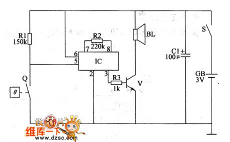
The frost alarm circuit is composed of the power supply circuit, control circuit and temperature detection alarm circuit, and it is shown in Figure 1. Power supply circuit consists of battery CB, power switch s and electric hot thermometer Q. The alarm circuit consists of the sound integrated circuit IC, resistors R2, R3, transistor V and the speaker BL. RI ~ R3 use the 1/4W metal film resistors or carbon film resistors. C selects the electrolytic capacitor with voltage in 6.3V. V uses the 59013 or CW9561-type audio integrated circuit. BL uses the 0.25W, 8Ω electric loudspeaker.
(View)
View full Circuit Diagram | Comments | Reading(1351)
Audio sonic door circuit diagram
Published:2011/8/11 1:42:00 Author:Ecco | Keyword: Audio sonic door
View full Circuit Diagram | Comments | Reading(845)
Temperature controller circuit diagram 1
Published:2011/8/15 1:25:00 Author:Ecco | Keyword: Temperature controller
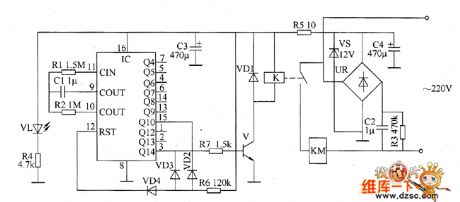
The intermittent controller circuit is composed of the power supply circuit, timer and control implementation circuit, and it is shown as the chart. Power supply circuit is composed of the capacitors C2 ~ C4, resistors R3 ~ R5, bridge rectifier UR, power regulator diode VS, and power indication light-emitting diode VL. The timer circuit is composed of counter / divider integrated circuit IC, capacitor C1, diodes VD2 ~ VD4 and resistors R1, R2, R6. R1, R2, C1 and IC internal circuit form the clock oscillator circuit, and the oscillation period (T) value is decided by R2 and C1. Control implementation circuit consists of the transistor V, resistor R7, diode VD1, AC contactor KM and relay K.
(View)
View full Circuit Diagram | Comments | Reading(890)
Three-phase AC constant phase sequence controller circuit diagram
Published:2011/8/15 21:40:00 Author:Ecco | Keyword: Three-phase AC , constant phase sequence , controller
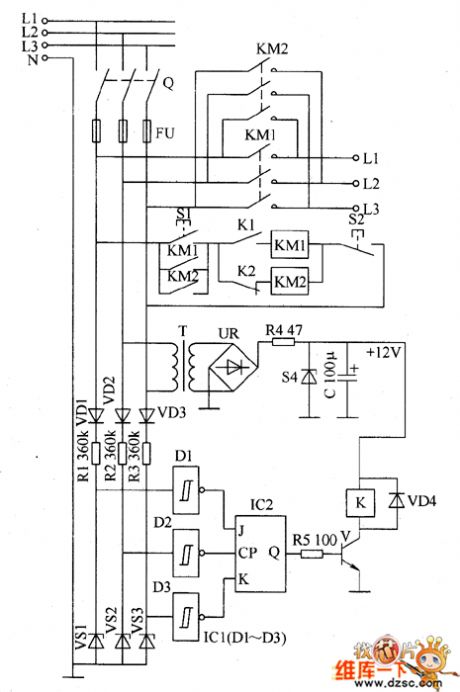
The three-phase AC constant phase sequence controller circuit is composed of the power supply circuit, phase detection circuit and control circuit, and it is shown as the chart. Power supply circuit consists of the power transformer T, bridge rectifier UR, resistor M, regulator diode VS4 and filter capacitor C. Phase sequence detection circuit consists of the rectifier diodes YD1 ~ VD3, current-limiting resistors R1 ~ R3, zener diodes VS1 ~ VS3 and Schmitt trigger NAND gate integrated circuit IC1 internal D1 ~ D3. The control circuit is composed of the JK flip-flop IC IC2, resistor R5, transistor V, diode VD4, relay K and AC contactors KM1, KM2.
(View)
View full Circuit Diagram | Comments | Reading(3848)
Demagnetizer energy-saving controller circuit diagram
Published:2011/8/11 1:09:00 Author:Ecco | Keyword: Demagnetizer, energy-saving controller
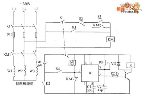
The demagnetizer energy-saving controller circuit is composed of the relay K, transistor V, time-base integrated circuit IC, diode VD, resistors R1, R2, potentiometer RP, capacitors C1, C2, battery GB, limit switch S4 and manual / automatic control switch S1, and other components, and it is shown as the chart. Knife switch Q, start button S3, stop button S2, contactor KM form the original manual for the demagnetizer machine control circuit. R1 and R2 select the 1/4W metal film resistors. RP uses the organic solid potentiometer. VD selects the 2CPl0 or 1N4007 silicon rectifier diodes.
(View)
View full Circuit Diagram | Comments | Reading(2516)
Pressure tank air pressure abnormality alarm circuit diagram
Published:2011/8/11 0:58:00 Author:Ecco | Keyword: Pressure tank , air pressure , abnormality alarm

The pressure tank air pressure abnormality detection alarm circuit is composed of the pressure control circuit, LED indication circuit and voice alarm circuit, and it is shown as the chart. The air pressure measurement and control circuit is composed of the power switch S, battery CB, electric contact pressure gauge Q. LED indicator circuit is composed of the green LED VL1, red light-emitting diode VL2 and resistors R1, R2. R1 ~ R3 select the t/4W metal film resistors or a carbon film resistors. C1 select the electrolytic capacitor with voltage in 16V: C2 uses the high-frequency ceramic capacitor. VD1 and VD2 use 1N4001 or 1N4007 type silicon rectifier diodes.
(View)
View full Circuit Diagram | Comments | Reading(2058)
Temperature controller circuit diagram 6
Published:2011/8/15 21:44:00 Author:Ecco | Keyword: Temperature controller
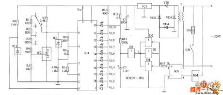
The temperature controller circuit is composed of the power supply circuit, temperature detection control circuit, LED indication circuit and heater control circuit, and it is shown as the chart. Power supply circuit is composed of the power transformer T, rectifier diodes VD1 ~ VD4, three-terminal voltage regulator integrated circuit IC5 and filter capacitor C1. Temperature detection control circuit is composed of the temperature sensor integrated circuit IC1, temperature control selector switch S, three-terminal voltage regulator integrated circuit IC2 and the resistors R1 ~ R6. LED temperature indicator circuit is composed of the voltage reference integrated circuit IC3, LED display driver integrated circuit IC4, resistors R8 ~ R13 and LEDs VL1 ~ VL10.
(View)
View full Circuit Diagram | Comments | Reading(1738)
Liquid level controller circuit diagram 2
Published:2011/8/15 22:14:00 Author:Ecco | Keyword: Liquid level controller
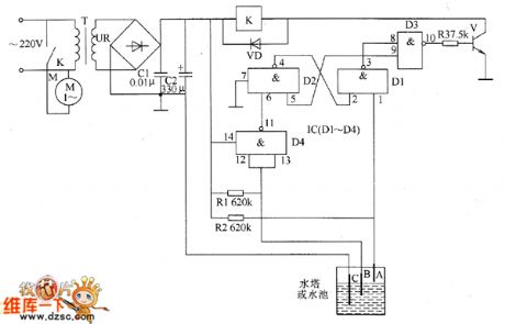
The liquid level controller circuit consists of the power supply circuit and level detection control circuit, and it is shown as the chart. Power supply circuit consists of the power transformer T, bridge rectifier UR and filter capacitors C1, C2. Liquid level detection control circuit consists of electrodes A ~ C, four NAND gate IC IC (D1 ~ D4), transistor V, resistors R1 ~ R3, relay K and diode VD. R1 ~ R3 select the 1/4W carbon film resistors or metal film resistors. C1 selects the monolithic capacitor with voltage in 63V: C2 selects the aluminum electrolytic capacitor with voltage in 25V.
(View)
View full Circuit Diagram | Comments | Reading(1812)
Intermittent controller circuit diagram 3
Published:2011/8/15 1:36:00 Author:Ecco | Keyword: Intermittent controller
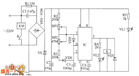
The intermittent controller circuit is composed of the power supply circuit, timing control circuit and control implementation circuit, and it is shown as the chart. The power supply circuit is composed of the step-down capacitor C1, resistors R1, R5, rectifier diodes VD1 ~ VD4, voltage regulator diode VS, power indicator LED VL1 and filter capacitor C2. Timing control circuit consists of the time-base integrated circuit IC, resistors R2 ~ R4, capacitors C3, C4, potentiometers RP1, RP2, diodes VD5, VD6 and light-emitting diode VL2. Control implementation circuit is composed of the diode VD7, AC contactor KM and relay K.
(View)
View full Circuit Diagram | Comments | Reading(670)
Intermittent controller circuit diagram 2
Published:2011/8/15 1:31:00 Author:Ecco | Keyword: intermittent controller
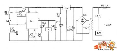
The intermittent controller circuit is composed of the power supply circuit, timing control circuit and control implementation circuit, and it is shown as the chart. Power supply circuit is composed of the fuse FU, power transformer T, bridge rectifier UR, filter capacitor C3, three-terminal voltage regulator integrated circuit IC2, current limiting resistor R1 and the power indicator LED VL1. Timing control circuit consists of the time-base integrated circuit IC1, potentiometers RP1 and RP2, resistor R2, working indication LED VL2 and capacitors C1, C2. Control implementation circuit consists of the relay K, AC contactor KM and diode VD.
(View)
View full Circuit Diagram | Comments | Reading(856)
Fish farming oxygen increasing controller 4
Published:2011/8/9 22:08:00 Author:Ecco | Keyword: Fish farming, oxygen increasing controller
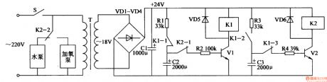
The fish farming oxygen increasing controller circuit is composed of the power supply circuit and control circuit, and it is shown in Figure 4-21. Power supply circuit is composed of the power switch S, power transformer T, rectifier diode VDl-VD4 and filter capacitor Cl. Control circuit consists of transistors Vl, V2, relays Kl, K2, resistors Rl-R4, capacitors C2, C3 and diodes VD5, VD6. RI-R4 select the 1/4W carbon film resistors or metal film resistors. Cl uses the aluminum electrolytic capacitor with voltage in 35V; C2 and C3 select the aluminum electrolytic capacitors with voltage in 25V. VDI-VD6 use 1N4007 silicon rectifier diodes. Vl and V2 choose C8050 or S8050 silicon NPN transistors.
(View)
View full Circuit Diagram | Comments | Reading(635)
Fish farming oxygen increasing controller 3
Published:2011/8/9 22:04:00 Author:Ecco | Keyword: Fish farming, oxygen increasing controller
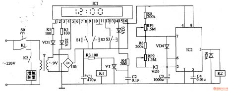
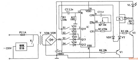
The fish farming oxygen increasing circuit is composed of the power supply circuit, clock-control timing circuit and intermittent control circuit, and it is shown in Figure 4-20. Power supply circuit consists of the power button S0, power transformer T, bridge rectifier UR and filter capacitor C1. Clock-control timing circuit is composed of clock-control board circuit ICl, resistors Rl-R4, diodes VDl-VD3, time set buttons S1-S3, SCR VT, relay Kl and capacitor C2. Intermittent control circuit is composed of the time-base integrated circuit IC2, resistors R5, R6, potentiometers RPl, RP2, capacitors C3, C4, diodes VD4-VD6 and relay K2.
(View)
View full Circuit Diagram | Comments | Reading(660)
Fish farming oxygen increasing controller 2
Published:2011/8/9 21:54:00 Author:Ecco | Keyword: Fish farming , oxygen increasing controller
The fish farming oxygen increasing circuit is composed of the power supply circuit, timing control circuit and control implementation circuit and working status indication circuit, and it is shown in Figure 4-19. Power supply circuit consists of the fuse FU, power transformer T, rectifier diodes VD6-VDg and filter capacitor Cl. Timing controller circuit consists of the timer integrated circuit IC, resistors Rl-R3, potentiometer RP, capacitors C2, C3, diodes VDl-VD4 and control switches Sl-S4. Control implementation circuit consists of the resistor R4, transistor Vl, diodes VD5, VDlO, thyristor VT and the relay K.
(View)
View full Circuit Diagram | Comments | Reading(631)
| Pages:88/312 At 2081828384858687888990919293949596979899100Under 20 |
Circuit Categories
power supply circuit
Amplifier Circuit
Basic Circuit
LED and Light Circuit
Sensor Circuit
Signal Processing
Electrical Equipment Circuit
Control Circuit
Remote Control Circuit
A/D-D/A Converter Circuit
Audio Circuit
Measuring and Test Circuit
Communication Circuit
Computer-Related Circuit
555 Circuit
Automotive Circuit
Repairing Circuit