
Index 89
Fish farming oxygen increasing controller 1
Published:2011/8/9 21:51:00 Author:Ecco | Keyword: Fish farming , oxygen increasing controller
The fish farming oxygen increasing circuit is composed of the power supply circuit and time control circuit, and it is shown in Figure 4-18. Power supply circuit consists of the power transformer T, rectifier diodes VDl-VD4, three-terminal voltage regulator integrated circuit ICl, filter capacitors Cl, C2, current limiting resistor Rl, and power indicator light-emitting diode VL. Timing control circuit consists of resistors R2-R4, potentiometer RP, diodes VD5-VD7, control switch S, capacitors C3, C4, transistors V, time-base integrated circuit IC2 and relay K. Rl-R4 select the 1/4W metal film resistors or carbon film resistors. RP uses the organic solid potentiometer.
(View)
View full Circuit Diagram | Comments | Reading(668)
Eggs hatching incubator circuit diagram 4
Published:2011/8/10 2:18:00 Author:Ecco | Keyword: Eggs hatching incubator
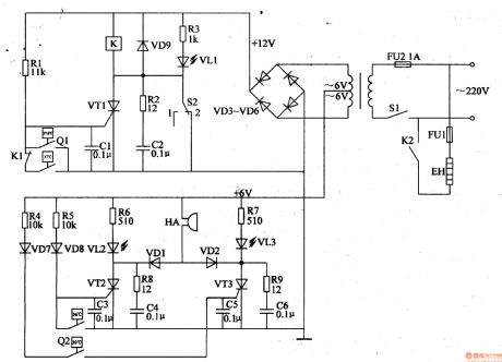
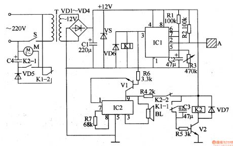
The eggs hatch incubator circuit is composed of the power supply circuit, constant temperature control circuit and sound and light alarm circuit, and it is shown in Figure 4-7. Power supply circuit consists of the power switch Sl, fuse FU2, power transformer T and rectifier diodes VD3-VD6. Temperature control circuit consists of the electric contact thermometer Ql, resistors Rl-R3, capacitors Cl, C2, thyristor VTl, diode VD9, relay K, light-emitting diodes VLl and manual / automatic switch S2. Sound and light alarm circuit consists of the electric contact thermometer Q2, resistors R4-Rg, capacitors C3-C6, transistors VT2, VT3, diodes VDl, VD2, VD7, VD8, light-emitting diodes VL2, VL3 and buzzer HA.
(View)
View full Circuit Diagram | Comments | Reading(5544)
Eggs hatching incubator 3
Published:2011/8/10 2:23:00 Author:Ecco | Keyword: Eggs hatching incubator
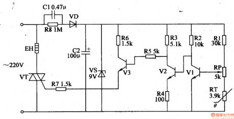
The eggs hatch incubator circuit is composed of the power supply circuit and temperature control circuit, and it is shown in Figure 4-6. The power supply circuit consists of the step-down capacitor Cl, discharge resistor R8, rectifier diode VD, filter capacitor C2 and zener diode VS. Temperature control circuit consists of the resistors Rl- R7, potentiometer RP, thermistor RT, transistor VT and thyristors Vl-V3. Rl-R8 select the 1/4W metal film resistors or carbon film resistors. RT uses the negative temperature coefficient thermistor. RP uses synthetic membrane potential, or precision multi-turn potentiometer.
(View)
View full Circuit Diagram | Comments | Reading(1478)
Microwave turn-off delay device
Published:2011/8/14 22:52:00 Author:Ecco | Keyword: Microwave , turn-off delay device
The microwave delay-off circuit is composed of the power supply circuit and delay control circuit, and it is shown in Figure 3-209. Power supply circuit consists of the nonstick button switch Sa, step-down capacitor Cl, resistor Rl, rectifier diodes VDl-VD4, voltage regulator diode VS and filter capacitor C2. Delay control circuit consists of op-amp integrated circuit IC, transistor V, relay K, delay capacitor C4, button switch Sb, current transformer TA, diodes VD5-VD7, resistor R7 and other components. Rl selects the 1/2W carbon film resistors; R2-R7 use the l/8W or 1/4W carbon film resistors.
(View)
View full Circuit Diagram | Comments | Reading(1550)
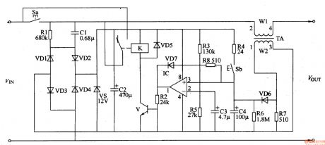
Water power off and open controller
Published:2011/8/8 21:42:00 Author:Ecco | Keyword: Water controller, power off , power open
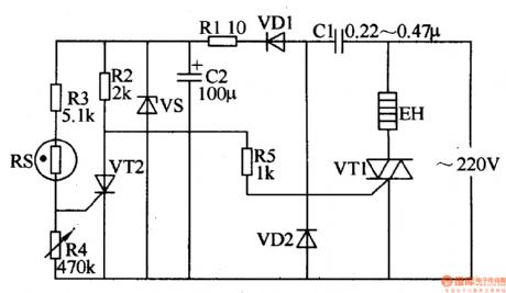
This water power off and open controller circuit described in the example is composed of the power supply circuit and control circuit, and it is shown in Figure 3-208. The power supply circuit consists of the step-down capacitor Cl, rectifier diodes VDl and VD2, current limiting resistor Rl, filter capacitor C2, Zener diode VS and other components. Control circuit consists of resistor R5, humidity sensitive resistor RS, thyristor Vn, Triac VTl. EH is the heater on the kettle. Rl chooses 2W metal film resistor; R2, R3, R5 select the 1/4W metal film resistors; R4 select the membrane variable resistor.
(View)
View full Circuit Diagram | Comments | Reading(760)
LBl690 high performance brushless DC motor control circuit diagram
Published:2011/8/15 20:42:00 Author:Ecco | Keyword: high performance , brushless , DC motor control
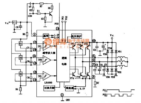
LBl690 is the three-phase brushless DC motor drive control integrated circuit produced by Japanese Sanyo, and it is widely used in domestic and imported broken wind , fresh air-condition brushless DC drive control. 1. FeaturesLBl690 IC has the over-current limiting, thermal shutdown circuit, HALL tape amplifier, FG output circuit. Pressure is 45V with 2.5 A current output. The manifold internal block diagram and typical application circuit are shown in Figure 1.
(View)
View full Circuit Diagram | Comments | Reading(5098)
AV equipment order open, shut down controller
Published:2011/8/11 20:17:00 Author:Ecco | Keyword: AV equipment, order open controller, shut down controller
The AV equipment order open, shut down controller circuit is composed of the power supply circuit and control circuit, and it is shown in Figure 3-207. Power supply circuit consists of the power transformer T, bridge rectifier UR, filter capacitors C6, C7, three-terminal voltage regulator integrated circuit, resistor R14 and power indicator LED VLl. Control circuit consists of the control switch S, resistors Rl-R13, capacitors Cl-C5, operational amplifier integrated circuit (Nl-N4), diodes VDl-VD4, transistors Vl-V4, relays Kl-K4 and outlets XSl-XS4. Rl-R14 select the 1/4W metal film resistors.
(View)
View full Circuit Diagram | Comments | Reading(631)
Electric fan anti-injured controller
Published:2011/8/14 22:44:00 Author:Ecco | Keyword: Electric fan , anti-injured controller
The electric fan anti-injured controller circuit is composed of the power supply circuit, touching power-off circuit, brake circuit and alarm circuit, and it is shown in Figure 3-206. Power supply circuit is composed of the power transformer T, rectifier diodes VDl-VD4, filter capacitor Cl and voltage-regulator diode VS. Touching power- off circuit is composed of touching pad A, time-base integrated circuit lCl, relay Kl and the RC components. Braking circuit is composed of the relay driver transistor V2, capacitors C3, C4 and resistor R5 and so on. Alarm circuit is composed of the music integrated circuit IC2, transistor Vl, speaker BL and resistors R4, R6 and so on.
(View)
View full Circuit Diagram | Comments | Reading(2229)
Washing machine electronic program controller
Published:2011/8/15 21:11:00 Author:Ecco | Keyword: Washing machine, electronic program controller
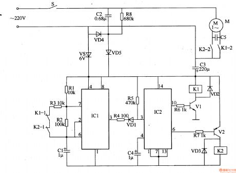
The washing machine electronic program controller circuit is composed of the power supply circuit, multivibrator, flip-flop and control implementation circuit, and it is shown in Figure 3-205. Power supply circuit is composed of the power switch S, buck capacitor C2, resistor R8, rectifier diodes VD4, VD5, voltage regulator diode VS and filter capacitor C3. Multivibrator integrated circuit is composed of the time-base ICl, resistors Rl-R3, capacitor Cl and the normally closed contacts Kl-l, K2-1 of relays Kl, K2. Trigger consists of the voice control circuit IC2, diode VDl, resistors R4, R5 and capacitor C4.
(View)
View full Circuit Diagram | Comments | Reading(5152)
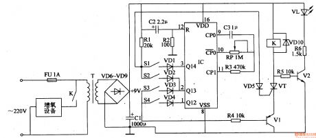
Single-button Ten-grade Timing Alarming Switch Circuit Diagram
Published:2011/8/9 17:56:00 Author:Vicky | Keyword: Single-button, Ten-grade, Timing Alarming Switch
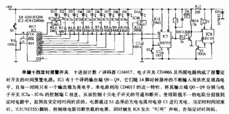
The time presetting circuit of the timing alarming switch is composed of decimal counter/decoder CD4017, electronic switch CD4066 and the peripheral circuits.IC1 has ten decoding output ends,Q0~Q9. They present high level in turn with the continuous input of 14 pin clock pulse. This circuit takes use of the feature of CD4017, and connects each of the output ends Q0~Q9 with the control end C of electronic switches IC2a~IC4b respectively so as to control these ten the electronic switches and enable the resistances of different resistance value to be connected with the timing circuit, which can reach the goal of changing the timing time. The power supply charges the capacitance C1 via the charging resistor chosen by S1. When the time is over, IC5 (NE555) spins, the control relay cuts off the laden power supply, and meanwhile the trigger IC6 gives out rub-a-dub sound to tell it’s time up. (View)
View full Circuit Diagram | Comments | Reading(1106)
Monolithic Alarming Timer Circuit Diagram
Published:2011/8/9 17:57:00 Author:Vicky | Keyword: Monolithic, Alarming Timer

Monolithic Alarming Timer
IC1 is a 14 decimals counter/frequency divider and oscillator, which can work in a relatively wider range of frequency. When S1 closes, R4 and C2 can generate positive pulse when are turned on, and reset the counter. Then it begins counting. When it comes to 14 decimals, the 3 pin represents high level, and T1 drives the piezoelectric buzzer to produce sound. The time delay function can be adjusted by P1. Then relationship between time delay and parameters of components is shown as follows:
1 ~ 30 min: C1= 200mF; P1= 500KΩ;
1 ~ 60 min: C1= 470mF; P1= 500KΩ;
1 ~ 200 min: C1= 470mF; P1= 1MΩ. (View)
View full Circuit Diagram | Comments | Reading(901)
Simple Precise Timer Circuit Diagram
Published:2011/8/9 17:59:00 Author:Vicky | Keyword: Precise Timer
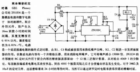
The circuit is a pluggable timer for delaying the time of conducting power supply, R1 and C1 constitutes filter to reduce the peak of the noise, and R2 and C2 work to further promote the performance of the filter. There is a shunt regulator within the integrated circuit to reduce the noise of power grid. It can reduce the noise to 15000 times less. There is a RC timing component which is connected with the periphery of 2N1034 to work with the precise oscillator to drive a 12-grade binary counter, so that it comes to the proportion of 4069:1. When the state of the trigger end or the voltage of power supply is changed, then the state of output is changed only after 4095 cycles of oscillating. As for timing components of 3MΩ and 10μF, it means it takes them 24 hours of waiting time. Certainly, the required precise delay time can be acquired by adjusting the timing resistance. (View)
View full Circuit Diagram | Comments | Reading(1008)
Diagram of Precise Timer composed by LM567 and MP1826
Published:2011/8/9 18:00:00 Author:Vicky | Keyword: Precise Timer
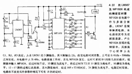
LM567 is a frequency demodulating circuit. The circuit uses it as a two-frequency oscillator to generate the low-frequency pulse required by MP1826. The frequency of the central oscillating
ƒ0 is determined by C1, R2 and R3. ƒ0 is output by 3 pin of LM567, and 2 ƒ0 output by 8 pin can change the time constant of the circuit. ƒ0 varies between 0.01Hz to 500kHz. In this circuit, ƒ0 is 4Hz. When the circuit is on, MP1826 firstly reset, and meanwhile D1 go out after twinkling several times. In the low-frequency pulse input MP1826, pin 10 changes to high level after T time, and pin 11 changes to high level while pin 10 changes to low level after another T2 time; pins from 12 to 17 work in the same manner. When the pin 8 is grounding, pin 24 changes to high level after a period of time of 105×T2. Then the timing of the circuit ends. If the parameters of the components remain unchanged, there are 18 grades of timing of the circuit. (View)
View full Circuit Diagram | Comments | Reading(2074)
Ultrasonic remote light switch circuit diagram
Published:2011/8/9 18:03:00 Author:Vicky | Keyword: ultrasonic, remote light switch
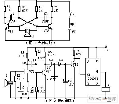
Picture 1 is a emitter circuit. The circuit uses discrete devices. VT1, VT1, R1, R2, R3, R4 , C1 and C2 constitute a self-excitation multivibrator. Ultrasonic emitting device B is connected in the collector loop of VT1 and VT2 to conduct push-pull work. The time of loop is often determined by R1, C1, R4 and C2. The resonance frequency of ultrasonic receptor device B triggers the multivibrator circuit. Hence, the circuit can work under optimized frequency.
Picture 2 is a receiving circuit, JFET VT1 constitutes high-input resistance amplifier, which performs better working with ultrasonic receptor device B and obtains higher receiving sensitiveness and better frequency-selecting performance. (View)
View full Circuit Diagram | Comments | Reading(1646)
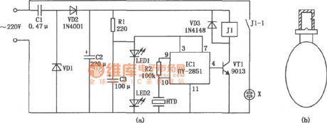
Light control automatic energy-saving LED lights circuit
Published:2011/7/20 7:33:00 Author:Fiona | Keyword: Light control, automatic energy-saving

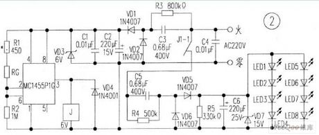
Circuit is shown in Figure 1,electrical schematic diagram is shown in Figure 2. The voltage AC220V is reduced by C3,R3 discharges,VD1 and VD2 rectify,C2 and C1 filter and get a smooth direct current,the voltage-regulator diode stabilizes the voltage in 6V and supplys the power for MC1455P1G and photosensitive resistor.In the daytime,photosensitive resistor RG is small in the light,② and ⑥ pins of MC1455P1G input high level,③ pin outputs low level,the relay J2 is off,the contact of J1-1 does not turn on, 220V voltage is not added on the capacitor C5,so the LED is not bright.
(View)
View full Circuit Diagram | Comments | Reading(2251)
motor flashing lights controller(4)
Published:2011/7/25 2:08:00 Author:chopper | Keyword: motor, flashing lights, controller
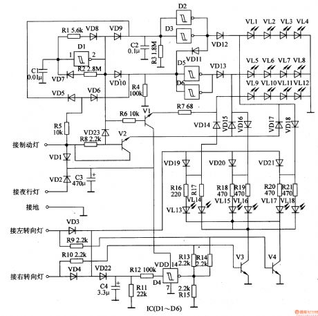
This example describes the motor flashing lights controller with three functions like lights cycle,braking flash,and steering flash,and it can be taken as the taillights' decorative lights of motorcycles or cars. The principle of circuit The motor flashing lights controller circuit includes low-frequency oscillator,brake/nocturnal light control circuit, turn light control circuit and LED circuit, just as 7-28 shows.
The low-frequency oscillator circuit consists of D1 within the Schmitt trigger integrated circuit IC (D1-D6) , resistors R1, R2, capacitor C1 and diodes VD7, VD8. Brake / nocturnal light control circuit is formed by the resistors R3-R8, capacitor C2, C3 diodes VD1, VD2, VD5, VD6, VD9-VD11, VD23 and crystals V1, V2.
(View)
View full Circuit Diagram | Comments | Reading(1013)
motor headlamp auto-changing controller(4)
Published:2011/7/25 2:10:00 Author:chopper | Keyword: motor, headlamp, auto-changing controller
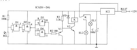
This example describes motor headlamp auto-changing controller produced by CD4011 digital integrated circuit,it can automatically transform the high beam and low beam of motor when the motors meet(turn the high beam into low beam),and it will resume after meeting.The principle of circuitThis motor headlamp auto-changing controller includes power supply circuit, optical control circuit,and control executive circuit,which is shown as picture7-4.
Power supply circuit is formed by the current limiting resistor R4, three-terminal voltage regulator integrated circuit IC2 and filter capacitor C. Light control circuit consists of resistor R1, photosensitive resistor RG and four nand-gate integrated circuits IC1 (D1-D4).
(View)
View full Circuit Diagram | Comments | Reading(733)
planter fertilization tube blockage alarm
Published:2011/7/25 1:04:00 Author:chopper | Keyword: planter, fertilization tube, blockage alarm
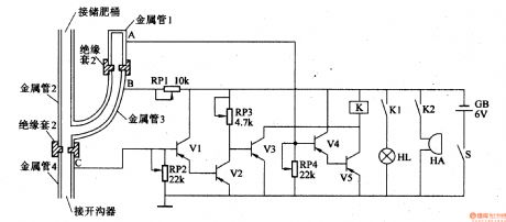
This example describes the planter fertilization tube blockage alarm,which can send the sound and light alarm signal to alert the staff to process timely when the fertilizertube is jammed. The principle of circuit The planter fertilization tube blockage alarm circuit is formed by the transistors V1-V5,the potentiometers RP1-RP4,relay K, indicator light HL,buzzer HA,power switch S and battery GB,which is shown in figure 4-106.
(View)
View full Circuit Diagram | Comments | Reading(728)
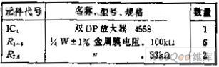
choosing operation mode by the input terminal adding and subtraction circuit
Published:2011/7/27 8:21:00 Author:Fiona | Keyword: input terminal, adding, subtraction, operation mode
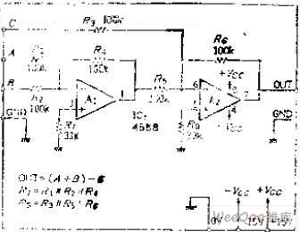
Circuit function
This is the PSD of match using silicon photodiodes.In order to reduce the error because of receiving flux,it usually carries out the operation A + B, and thus to control the laser diode power. This circuit uses the common circuit module that can add and subtract, which has 3 inputs, but has different functions,for example, only the A and B input, it's a common additive A + B circuit; if it uses C to input and uses one between A and B,you can subtract.
Circuit Work
This addition and subtraction circuit is composed of the inverse OP amplifier circuit, the output voltage EO can express by the following formula:
Under this formula, if assuming the resistance R1 ~ R6 are equal, you can to do the addition and subtraction operations that the magnification is 1.
In the inverting amplifier, the input resistor is the input impedance, if it needs high input resistance, OP amplifier should be replaced by BI-FET type, such as the TL082, etc., and removes the resistors R7, R8. (View)
View full Circuit Diagram | Comments | Reading(740)
The sub-ultrasonic remote control switch circuit
Published:2011/8/1 22:03:00 Author:TaoXi | Keyword: Sub-ultrasonic, remote control switch
The sub-ultrasonic remote control switch circuit is as shown:
(View)
View full Circuit Diagram | Comments | Reading(713)
| Pages:89/312 At 2081828384858687888990919293949596979899100Under 20 |
Circuit Categories
power supply circuit
Amplifier Circuit
Basic Circuit
LED and Light Circuit
Sensor Circuit
Signal Processing
Electrical Equipment Circuit
Control Circuit
Remote Control Circuit
A/D-D/A Converter Circuit
Audio Circuit
Measuring and Test Circuit
Communication Circuit
Computer-Related Circuit
555 Circuit
Automotive Circuit
Repairing Circuit