
Index 93
Dual high and low temperature limit controller circuit diagram
Published:2011/8/4 20:42:00 Author:Rebekka | Keyword: Dual high temperature , limit controller, Dual low temperature
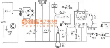
The circuit is composed of a D flip-flop of the dual D CD4013 flip-flop. The structure is simple with the feature of high and low temperature control. The control temperature can be preset by the potentiometer, when the temperature is more than the preset temperature, the power will be automatically cut off. It can be used for the industrial heating processing equipments. The constitution of circuit is shown as above. D flip-flop in the circuit will be connected to a RS flip-flop. It uses thermistor MF51 used by industrial control as temperature sensors. (View)
View full Circuit Diagram | Comments | Reading(1328)
The overcurrent protection of DC circuit diagram
Published:2011/8/4 20:45:00 Author:Rebekka | Keyword: DC circuit, overcurrent protection
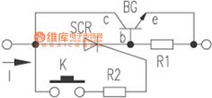
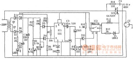
Electronic protection circuit is shown in the figure. When the micro switch K is connected to the power supply, the one-way thyristor SCR and the DC circuit will be turned on. When the power consumption excees the the allowable value, the voltage of the sense resistor R1 is greater than 0.7V, the transistor BG is turned on,the voltagebetween collector C and base b of the transistor drops belowthe sustaining voltage of 3CT. 3CT will be turned off and the power supply circuit will be cut off. Electronic protection circuit has a high-speed drying, easy recovery characteristics. It can be applied to any DC circuit for overcurrent protection equipment. (View)
View full Circuit Diagram | Comments | Reading(1648)
The battery protector with voltage charging circuit composed of 555
Published:2011/8/4 20:32:00 Author:Rebekka | Keyword: battery protector , voltage charging circuit
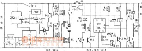
Discharge protection circuit consists of IC2 (555) and BG2, BG3, BG4 and so on. When the battery discharges to 10.5V, the regulators DW1, DW4 are regulatedto make BG2, BG4 stop. IC2 is reset becausepin ②, ⑥ are in high level; pin③ outputs low so BG3 stops. The release of relay J2 and the contact of J2-2 off (down) achieve the discharge protection. When the battery voltage is greater than 11.5V, IC2 sets, BG3 conducts, J2 pulls in, the load starts to work. When a load short circuit occurs, IC2 resets because pin ④ isin a low level. J2 releases. The short-circuit protection works. (View)
View full Circuit Diagram | Comments | Reading(830)
DC regulated power supply protection circuit composed of 555
Published:2011/8/4 20:38:00 Author:Rebekka | Keyword: DC regulated, power supply protection
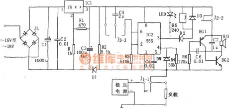
Monostable delay circuit is composed of the IC2 (555), R3, C4 and other components. Usually, J1-1 NC contact closes, the load makes IC2 ④ feet in a high potential (1V above), when the load is short circuit, 555 feet will be forced to reset because the ④ (<0.6V) level is low. ③ pin output high level to release the relay J. Contact J1-1 is connected. If it is still short circuit, it will be protected. (View)
View full Circuit Diagram | Comments | Reading(871)
Electrical equipment overload and open-phase protection device circuit composed of 555
Published:2011/8/4 20:39:00 Author:Rebekka | Keyword: Electrical equipment overload , open-phase protection device
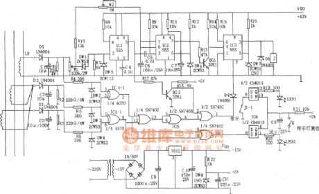
The device is composed of +12 V, +5 V DC power supply, AC transformer, voltage comparator, block timer, relay control circuit and phase loss protection circuits and other components. LH makes three-phase AC transformer current flowing couple in proportion, and they pass D1C1, D2C2, D3C3 rectifier filters and are added to the voltage comparator (IC1, DW1, DW5, R7) and phase-failure protection circuit (IC4, IC5, IC6). The phase loss protection circuit is composed of IC4 (CD4070), IC5 (7402), IC6 (CD4013). It is used for detecting and determine whether the three-phase current, if a phase-off phase, the IC3 will be set, the relay J Pick-up, the device will be cut off and the phase protection works. (View)
View full Circuit Diagram | Comments | Reading(2359)
Automatically reset earth leakage protector circuit composed of NE555
Published:2011/8/4 20:03:00 Author:Rebekka | Keyword: earth leakage protector

Signal detection circuit is the zero sequence current transformer composed of L1, L2, L3 and the magnetic core. Under normal circumstances, the total magnetic flux in the transformer is 0. When someone is shocked by the electric, the power supply passes the body to the ground, the current flowing of L1, L2 are different. Zero-sequence transformer in the magnetic flux induced in the L3 has an alternating voltage, and it is rectified by D1 and added to BG's base, so that BG saturated conduction, and 555 feet ois set because of potential ② low (<1 / 3VDo). (View)
View full Circuit Diagram | Comments | Reading(4267)
Automatic power protector circuit composed of 555
Published:2011/8/4 20:03:00 Author:Rebekka | Keyword: Automatic power protector, 555
The figure shows the automatic power protection circuit. The protector is composed of the buck rectifier circuit, overvoltage and undervoltage detection circuit, delay switch control circuit. The buck rectifier circuit provides DC voltage for the entire circuit. (View)
View full Circuit Diagram | Comments | Reading(909)
Automotive electronic password lock circuit diagram
Published:2011/8/4 21:35:00 Author:Rebekka | Keyword: Automotive electronic password lock
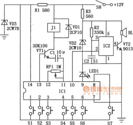
Automotive electronic code lock circuit is shown as above. ICl is exclusive lock for the integrated circuit 5G058, its ① ~ ⑥ feet connect external key switch to the power supply. They are six valid input keys. The unlock must follow the sequence of Sl ~ S6; pin ⑧ button switch S7 is connected to the false key input. It is free to pick one or a few keys on the keyboard plugged in as real mixed; pin⑨ is the key indication side, each key will cause the external connectivity in the light-emitting diode LEDl. (View)
View full Circuit Diagram | Comments | Reading(2521)
Multi-function household electrical appliances protection circuit diagram
Published:2011/8/4 21:34:00 Author:Rebekka | Keyword: household electrical appliances, protection circuit
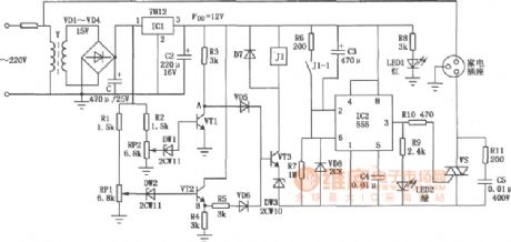
The circuit is composed of DC circuit, delay circuit, overvoltage and undervoltage protection circuit etc. ICl integrated circuit LM7812 outputs +12 V voltage. Undervoltage and overvoltage sample protection circuit is composed of sampling R2, potentiometer RP2, the regulator DWl, VTl and Rl, RPl, DW2, VT2, VD5, VD6, VT3 and control relay J1. In the figure, VT1 ~ VT3 use 3DG4, thyristor VS uses 6A/400V, VD1 ~ VD7 use 1N4004, relay J1 uses JRC-1M 12V.
(View)
View full Circuit Diagram | Comments | Reading(2483)
Electric steam iron temperature controller
Published:2011/8/5 2:04:00 Author:Ecco | Keyword: Electric steam iron , temperature controller
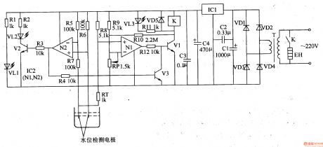
The electric steam iron temperature controller circuit is composed of the power supply circuit, water level detection circuit, temperature detection circuit and control implementation circuit, and it is shown in Figure 3-82. Power supply circuit is composed of the power transformer T, rectifier diodes VDl-VD4, resistor Rl, power indicator LED VLl, filter capacitors Cl-C4 and three-terminal voltage regulator integrated circuit ICl. Water detection circuit is composed of the the Nl which is inside of the operational amplifier integrated circuit IC2 (Nl, N2), transistor Vl, light-emitting diode VL2, resistors R2, R3, R5-R7, and the water level detection electrodes.
(View)
View full Circuit Diagram | Comments | Reading(4718)
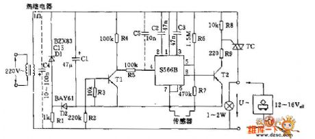
Electric water heater temperature controller
Published:2011/8/5 2:08:00 Author:Ecco | Keyword: Electric water heater , temperature controller
The electric water heater temperature controller circuit is composed of the power supply circuit, leakage protection circuit, temperature control circuit, water level indication and anti-dry circuit, and it is shown in Figure 3-81. Power supply circuit is composed of the power transformer T, bridge rectifier UR, filter capacitors Cl, C2, and three-terminal voltage regulator integrated circuit ICl. Leakage protection circuit is composed of the current transformer TA, a time-base circuit which is inside of the dual time-base integrated circuit IC2 (lC2a, IC2b), and some other peripheral components. Temperature control circuit consists of the another time-base circuit which is inside of the dual time-base integrated circuit lC2, thermistor RT, transistor V, Relay K, potentiometer RP and the other external components.
(View)
View full Circuit Diagram | Comments | Reading(803)
Refrigerator temperature controller 2
Published:2011/8/5 2:56:00 Author:Ecco | Keyword: Refrigerator temperature controller
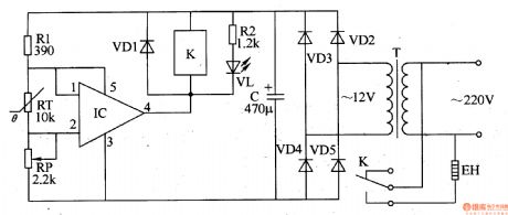
The refrigerator temperature controller circuit is composed of the power supply circuit and temperature detection control circuit, and it is shown in Figure 3-75. Temperature detection control circuit is composed of the thermistor RT, potentiometer RP, integrated electronic switch IC, resistors R1, R2, diode VDl, potentiometer K and working indicating LED VL. Power supply circuit is composed of the power transformer T, rectifier diode VL. Rl and R2 select 1/4W or 1/8W carbon film resistors. RP chooses the linear (X-type) potentiometer. C selects the aluminum electrolytic capacitor with the voltage in 16V. RT uses MF5l negative temperature coefficient thermistor. VDl-VD5 choose 1N4007 silicon rectifier diodes.
(View)
View full Circuit Diagram | Comments | Reading(2488)
Refrigerator temperature controller 1
Published:2011/8/5 2:52:00 Author:Ecco | Keyword: Refrigerator temperature controller
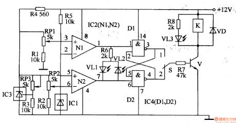
The refrigerator temperature controller circuit is composed of the temperature detection circuit, trigger and control implementation circuit, and it is shown in Figure 3-74. Temperature detection circuit consists of precision voltage regulator integrated circuit lC3, temperature sensor integrated circuit ICl, operational amplifier integrated circuit IC2 and resistors Rl-R5, potentiometers RPl-RP3. Trigger is composed of AND gate integrated circuit lC4, resistor R6 and light-emitting diodes VLl, VL2. Control implementation circuit is composed of the transistor V, heating / cooling control selector switch S, resistors R7, R8, relay K, light-emitting diodes VL3 and diode VD.
(View)
View full Circuit Diagram | Comments | Reading(1944)
Inverse-Counting Digital-Display Timing Controller (CD40110 And CD4040 And CD4069) Circuit
Published:2011/8/4 5:54:00 Author:Robert | Keyword: Inverse-Counting, Digital-Display, Timing, Controller
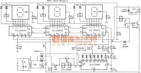
By using the AC power's 50Hz output frequency for frequency demultiplication, it could get kinds of different frequency's time-base pulses. This circuit uses lmin's time length as the timer's time-base standard. By the counter's counting, decoding and finally the nixietube would display the time. The circuit uses inverse-counting timing mode. The user should firstly predetermine the needed timing time by presetting the switch. Then by the subtraction counting to reduce the predetermined time step by step. When the predetermined time is reduced to 0, the counter would stop counting and output the control signal to make the relay have a action. Bucause the circuit can choose the presetting timing on or timing off, so it is very easy to use. Its circuit is shown in the picture. (View)
View full Circuit Diagram | Comments | Reading(8396)
Timing Circuit Composed Of Quartz Electronic Clock IC
Published:2011/8/4 8:06:00 Author:Robert | Keyword: Timing, Quartz, Electronic Clock, IC
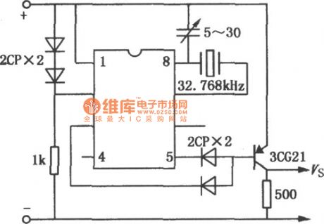
The pulse signal, which provided from the quartz electronic clock IC, has high accuracy. So it is widely used not just in quartz electronic clock, but also in time-base circuit and timing circuit. The picture shows the second pulse signal generator principle circuit composed of quartz electronic clock IC. The IC's working voltage is provided from positive voltage drop of two rectifier diodes (2CP). The power could be selected during 1.5V~15V. And also two detector diodes (2CP) and a triode (3CG) make up the NAND gate logic circuit. When the circuit is working, the output port (triode's collector polar) could get sable and accurate second signal. The circuit is connected a external 32.768kHz quartz crystal and a 5~20pF variable capacitor for frequency micro-adjustment. The quartz electronic clock IC can use the low-frequency type clock circuit, such as H5544 or LH5093 and so on. (View)
View full Circuit Diagram | Comments | Reading(3093)
Low Supply Voltage Thyristor Control Circuit
Published:2011/8/4 9:18:00 Author:Robert | Keyword: Low, Supply, Voltage, Thyristor, Control
This circuit's power supply voltage is 12~16V which can be used in toy trains and other low voltage devices. By using S566B as the trigger circuit which control the conduction of the thyristor. The DC power is provided by rectifier regulator circuit. The R1 is voltage dropping resistor which make the regulator has very low voltage. The middle transistor T1's function is reduce the control dead zone. Because the circuit's loading current is very low, however the bidirectional transistor's current is higher than its maintaining current, it could connect a 1~2W lamp. Because the transformer's output power is very low, in the moment of the conduction of the bidirectional transistor, for the fast increasing current, the transformer's leakage inductance is equivalent to a large series resistor, which would cause a short-term voltage discontinuous case. So it should connect a capacitor C4 in series (dotted line). (View)
View full Circuit Diagram | Comments | Reading(1083)
Electric fence control circuit
Published:2011/8/5 2:46:00 Author:Ecco | Keyword: Electric fence control
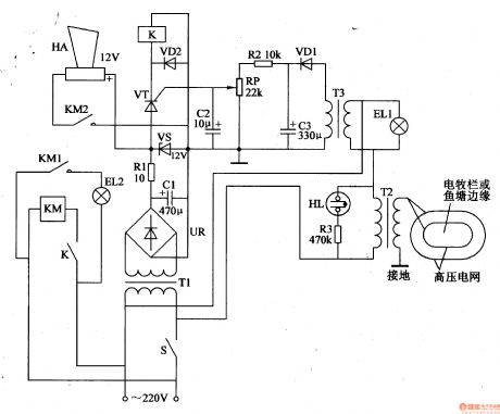
The electric fence control circuit is composed of the power supply circuit, high voltage circuit and sound and light alarm circuit, and it is shown in Figure 4-26. Power supply circuit is composed of the power switch S, the power transformer Tl, bridge rectifier UR, filter capacitor Cl, current limiting resistor Rl and the voltage regulator diode VS. The high-voltage consists of step-up transformer T2, neon light HL, resistor R3, lighting ELl and the secondary winding of power transformer T3. Sound and light alarm circuit consists of the T3, thyristor VT, diodes VDl, VD2, resistor R2, capacitors C2, C3, potentiometer RP, relay K, AC contactor KM, light EL2 and alarm HA.
(View)
View full Circuit Diagram | Comments | Reading(4260)
The temperature controller 4
Published:2011/8/5 2:24:00 Author:Ecco | Keyword: temperature controller
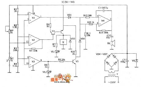
The temperature controller circuit is composed of the power supply circuit, the temperature detection control circuit and over-temperature alarm circuit, and it is shown as the chart. Power supply circuit is composed of the power transformer T, rectifier diodes VD4 ~ VD7, filter capacitor C3 and Zener VS. Temperature detection control circuit consists of the N1 ~ N3 which are inside of four operational amplifier integrated circuit IC (M ~ N4), resistors R1 ~ R1O, transistors V1 ~ V3, potentiometer RP, thermistor RT, LEDs VL1, VL2, diode VD2 and relay K. VD1 ~ VD3 select 1N4l48 silicon switching diodes; VD4 ~ VD7 select 1 N4007 silicon rectifier diodes.
(View)
View full Circuit Diagram | Comments | Reading(994)
Keeping Recording Continuous Sound Control Circuit
Published:2011/8/5 19:01:00 Author:Robert | Keyword: Keeping, Recording, Continuous, Sound Control
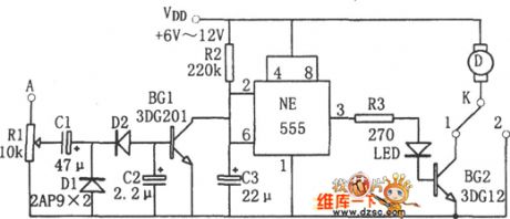
The picture shows the keeping recording continuous sound control circuit. This circuit's key point is the monostable delay circuit which is made up by 555 and R2, C3. The sound recording signal is added on the A port for input. When the A port has no sound recording signal input, the transistor BG1 would be not conducted to make the 555's pin 6 be high voltage level. So the 555 resets and output low voltage level on pin 3. And the BG2 is correspondingly not conducted and the motor is not working for recording. When the A port has sound recoding signal input, the D1, D2, C2 are processing for voltage doubler rectifier. And the BG1 is correspondingly saturated and conducted. The pin 2 would be in low voltage level (<1/3VDD) to make the 555 set. The pin 3 would output high voltage level so that the BG2 is also saturated and conducted. The motor D is electrified and then it is working for recording. (View)
View full Circuit Diagram | Comments | Reading(702)
INDEPENDENT_PULSE_WIDTH_CONTROL
Published:2009/7/14 21:42:00 Author:May
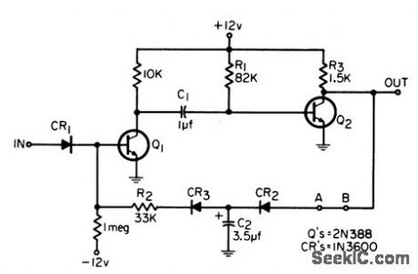
With components shown, circuit will divide 50-millisec pulses by 5 without changing pulse width. Other components give different widths along with division.-J. McGruder, Frequency Divider With Independent Pulse-Width Control, EEE, 14:2, p 69. (View)
View full Circuit Diagram | Comments | Reading(897)
| Pages:93/312 At 2081828384858687888990919293949596979899100Under 20 |
Circuit Categories
power supply circuit
Amplifier Circuit
Basic Circuit
LED and Light Circuit
Sensor Circuit
Signal Processing
Electrical Equipment Circuit
Control Circuit
Remote Control Circuit
A/D-D/A Converter Circuit
Audio Circuit
Measuring and Test Circuit
Communication Circuit
Computer-Related Circuit
555 Circuit
Automotive Circuit
Repairing Circuit