
Staircase Control
Index
Colourful Lights Controller Twenty-nine
Published:2011/8/12 4:50:00 Author:Felicity | Keyword: Colourful Lights Controller
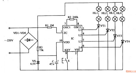
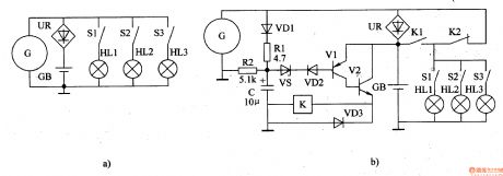
This colourful lights controller contains SH804 or SH805 colourful lights oriented controller IC.SH-804,SH-805 are the same with SH803 in shape,inner circuit and application circuit, while the stored control program and the function of pins are different. SH-804 has 10 lights repetition modes and 6 change speeds.The modes can cycle automatically or be set by control buttons. SH-805 has 16 repetition modes which can be set by control buttons. The application circuits of SH-804 and SH-805 are shown in Fig.1-144 and Fig.1-145,the select of components of which can refer to the application part of SH-803. (View)
View full Circuit Diagram | Comments | Reading(993)
Circulatory timing flashlight circuit diagram
Published:2011/9/6 21:09:00 Author:Vicky | Keyword: circulatory timing flashlight
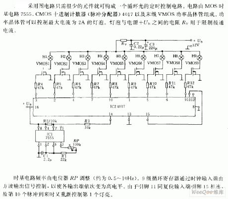
In accordance with the picture, the circulatory timing control circuit can be composed of very few components. The circuit is composed of MOS time base circuit 7555, CMOS decimal counter (pulse distributor) 4017 and last-stage VMOS power transistor. Power transistor can control lamp bulb of current up to 2A. The resistance Rave between the lamp bulb and power +UB is used to control the current.
The time base circuit frequency is modulated by potentiometer RP (about 0.5 ~ 10Hz), and the nine-stage circulatory register is controlled by the square wave output signal via clock input end, so as to make every output ends turn to high level in turn. Because the pin11 reset input end is connected with pin 15, the first lamp gives out light when the 10th pulse comes.
(View)
View full Circuit Diagram | Comments | Reading(1363)
motor flashing lights controller(4)
Published:2011/7/25 2:08:00 Author:chopper | Keyword: motor, flashing lights, controller
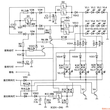
This example describes the motor flashing lights controller with three functions like lights cycle,braking flash,and steering flash,and it can be taken as the taillights' decorative lights of motorcycles or cars. The principle of circuit The motor flashing lights controller circuit includes low-frequency oscillator,brake/nocturnal light control circuit, turn light control circuit and LED circuit, just as 7-28 shows.
The low-frequency oscillator circuit consists of D1 within the Schmitt trigger integrated circuit IC (D1-D6) , resistors R1, R2, capacitor C1 and diodes VD7, VD8. Brake / nocturnal light control circuit is formed by the resistors R3-R8, capacitor C2, C3 diodes VD1, VD2, VD5, VD6, VD9-VD11, VD23 and crystals V1, V2.
(View)
View full Circuit Diagram | Comments | Reading(1023)
motor headlamp auto-changing controller(4)
Published:2011/7/25 2:10:00 Author:chopper | Keyword: motor, headlamp, auto-changing controller
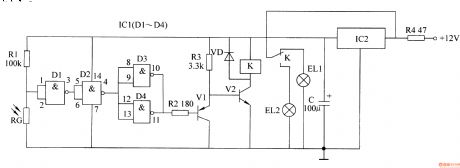
This example describes motor headlamp auto-changing controller produced by CD4011 digital integrated circuit,it can automatically transform the high beam and low beam of motor when the motors meet(turn the high beam into low beam),and it will resume after meeting.The principle of circuitThis motor headlamp auto-changing controller includes power supply circuit, optical control circuit,and control executive circuit,which is shown as picture7-4.
Power supply circuit is formed by the current limiting resistor R4, three-terminal voltage regulator integrated circuit IC2 and filter capacitor C. Light control circuit consists of resistor R1, photosensitive resistor RG and four nand-gate integrated circuits IC1 (D1-D4).
(View)
View full Circuit Diagram | Comments | Reading(745)
LED sign decorative light(4)
Published:2011/7/25 2:13:00 Author:chopper | Keyword: LED sign, decorative light
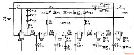
This example describes the LED sign decorative light,which can be made into the electronic road sign in theater,dance hall and other public places, as the safe passage in the bathroom. The principle of circuit The LED sign decorative light circuit is formed by the LEDs VL1-VL8, six non-gate integrated circuit IC (D1-D6), resistors B1-R12 and capacitors C1-C5, which is shown in Figure 1-156
The circuit adopts 9V laminated battery,and can also use the regulated power supply formed by capacitor C6, C7, resistor R12, rectifier diodes VD1, VD2 and a voltage-regulator diode VS
(View)
View full Circuit Diagram | Comments | Reading(2006)
LED sign decorative light(3)
Published:2011/7/20 0:13:00 Author:chopper | Keyword: LED sign, decorative light
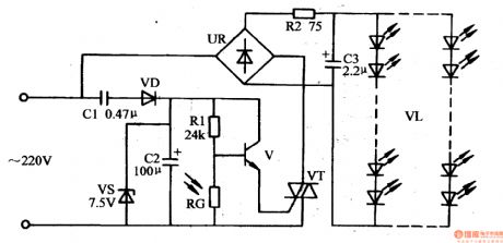
This example describes light-controlled LED sign decorative light which adopts divided components.And it does not work during the day, and automatically lights up at night, which is of traits like low power consumption, long life, maintenance-free, easy to make and so on. The principle of circuitThe LED sign decorative light circuit is formed by the power supply circuit, light-controlled circuit and LED display circuit,which is shown in Figure 1-155. The power supply circuit is formed by the capacitor C1, rectifier diode VD, voltage regulator diode VS and filter capacitor C2.
(View)
View full Circuit Diagram | Comments | Reading(2162)
LED sign decorative light(2)
Published:2011/7/20 0:44:00 Author:chopper | Keyword: LED sign, decorative light
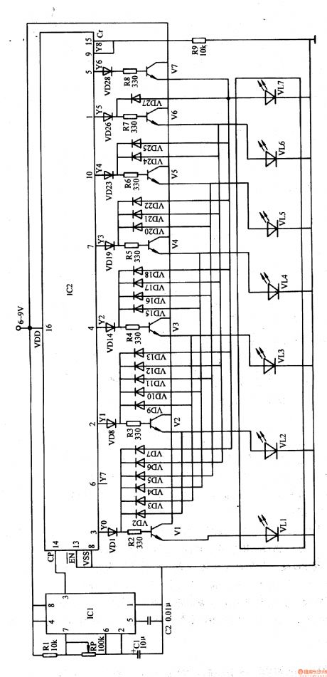
This example describes the LED sign decorative light,which uses some LEDs to form some words(for example, Please don't spit ). When the power is available, the seven characters light up one by one,finally they form Please do not spit , and then seven characters all turn off,then repeat the next cycle. The principle of circuit The LED sign decorative light circuit is formed by the clock generator, count distributor and LED display drive circuit, which is shown in Figure 1-154
(View)
View full Circuit Diagram | Comments | Reading(1022)
LED sign decorative light(1)
Published:2011/7/20 4:45:00 Author:chopper | Keyword: LED sign, decorative light
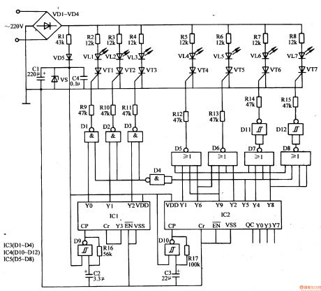
This example describes the LED sign decorative light,which is used to decorate all kinds of doors mark,road sign and emergency exit,fire access and other signs, and it can produce effects like text flashing,border flowing,and it will play a role of eye-catching, decorative effects. The principle of circuitThe LED sign decorative light circuit is formed by the power supply circuit,light flowing control circuit and text flashing control circuit, which is shown in Figure 1-153. Power supply circuit is formed by the rectifiers diodes VD1-VD5, resistor R1, voltage regulator diode VS and filter capacitor C1, C4.
(View)
View full Circuit Diagram | Comments | Reading(1740)
motor headlight auto-changing controller(II)
Published:2011/7/19 23:36:00 Author:chopper | Keyword: motor, headlight, auto-changing controller
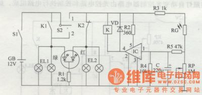
Principle of the circuit The motor headlight auto-changing controller circuit is formed by the optical detection circuit,control implementation circuit and LED indication which is shown in figure 7-2. Photoelectric detection circuit is formed by the photosensitive resistor RG,resistors R3-R5,capacitor C and the potentiometer RP. Control implementation ircuit is formed by the electronic switching integrated circuit IC,resistor R2,diode VD and relay K. LED indication circuit is formed by resistors Rl and color-changing light-emitting diode VL. S1 is the switch of vehicle key, S2 is the vehicle switch of turn light.
(View)
View full Circuit Diagram | Comments | Reading(611)
headlamp delay shutoff device
Published:2011/7/14 20:44:00 Author:chopper | Keyword: headlamp, delay shutoff
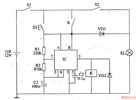
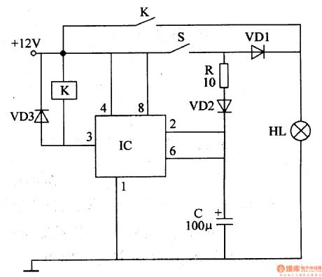
This example describes the headlamp delay shutoff device, and the headlamps can continue lighting a period of time before they close automatically when drivers press the delay button,thus it can offer a short time emergency lighting when the drivers park and leave in the night. The principle of circuit The headlamp delay shutoff device circuit includes the delay button S3,resistors R1,R2,capacitor C1,C2,diode VD1,VD2, relay K and time-base integrated circuit IC,which is shown in figure 7-32 . EL is the motor headlamp,S1 is the total power switch for the automotive,and S2 is the headlamp switch.
(View)
View full Circuit Diagram | Comments | Reading(718)
motor headlamp auto-changing controller(3)
Published:2011/7/19 23:36:00 Author:chopper | Keyword: motor, headlamp, auto-changing controller
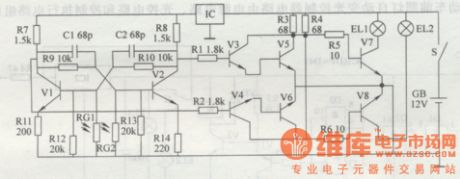
According to traffic safety rules,it should open high beam (bright light) when motors drive at night,but it should open low beam(weak light) when motors meet.Thus,drivers sholuld control the operation light by hands or feet several times when it meets at every time.This example describes motor headlamp auto-changing controller produced by discrete components,and it can automatically transform the high beam and low beam of motor when the motors meet to decrease the intensity of labour of drivers,and ensure safety. The principle of circuit The controller circuit consists of bistable trigger circuit and switching control circuit,which is shown in figure 7-3.
(View)
View full Circuit Diagram | Comments | Reading(717)
Brightness automatic control circuit
Published:2011/7/19 8:15:00 Author:Fiona | Keyword: automatic control
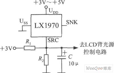
When the ambient brightness turns dark obviously,LX1970 can automatically turn the LCD backlight to make white LED light.Brightness automatic control circuit is shown as above.Using resistors R1 and R2 can set to control the brightness's minimum and maximum.Changing the capacity of capacitor C the capacity can adjust the response time and filter out 50 Hz power grid interference.LX1970 uses +3.3 ~ +5 V power supply.When only using SRC end,SNK end should be hung in the air.Assumed that the circuit requires 0.25 ~ 1.25V output voltage to drive the white LED,0.25V represents the minimum of LED brightness,1.25V represents the brightness's maximum.
(View)
View full Circuit Diagram | Comments | Reading(733)
brake lamp delay arrester
Published:2011/7/12 22:30:00 Author:chopper | Keyword: brake lamp, delay arrester
Brake lamp of general motor will light when the brake switch is trampled,and it will extinguish immediately when the brake switch is released.This example describes the brake lamp delay arrester, which can make brake lamp light for some time before it gose out when the brake switch is released,and it can avoidthe vehicle rear-end collision efficiently,and increase traffic safety. The principle of circuitThis brake lamp delay arrester includes time-base integrated circuit IC,relay K,capacitor C and diode VD1-VD3,which is shown as figure 7-34.
(View)
View full Circuit Diagram | Comments | Reading(670)
motor headlight auto-changing controller circuit(I)
Published:2011/7/12 0:40:00 Author:chopper | Keyword: motor, headlight, auto-changing controller,
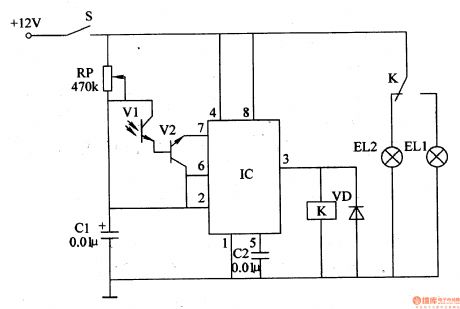
Principle of the circuit The motor headlight auto-changing controller circuit consists of light control circuit and control implementation circuit, which is shown in figure 7-1.
Light control circuit is formed by the photosensitive transistor Vl,transistor V2,potentiometer RP,capacitors Cl and C2 and the time-base integrated circuit IC. Control implementation circuit is formed by 3 feet inner circuit of IC, relay K and diode VD. (View)
View full Circuit Diagram | Comments | Reading(776)
instrument-panel lamp dimmer
Published:2011/7/12 22:29:00 Author:chopper | Keyword: instrument-panel lamp, dimmer
Drivers may feel very harsh at the moment the instrument-panel lamp is open at night.This example describes the instrument-panel lamp dimmer,which can reduce the visual impact of the drives,thereby it can enhance the safety of night driving. The principle of circuitThe instrument-panel lamp dimmer circuit is formed by the voltage regulator circuit,reset circuit,square-wave oscillator,protection circuit and electronic switching circuit,which is shown in figure 7-35. Regulator circuit consists of resistorsR1 and the voltage regulator diode VS. Reset circuit consists of capacitor C1, resistors R3, R4.
(View)
View full Circuit Diagram | Comments | Reading(743)
Auto Flash Alarm
Published:2011/7/10 23:50:00 Author:Felicity | Keyword: Auto Flash, Alarm
Work of the circuit
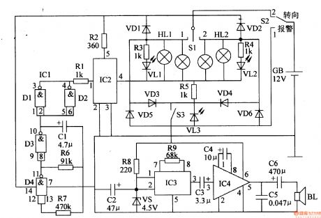
The circuit consists of low-frequency oscillator, the electronic switch circuit, control circuit, photoelectric display circuit and music alarm circuit. (It is showed in picture 7-113.)
Low-frequency oscillator consists of IC lCl (Dl-D4) internal NAND gate circuit D3, D4 and external RC components.
Control circuit consists of ICl internal non-gate Dl and D2. It is used to control high-power electronic switch IC lC2.
Photoelectric display circuit consists of diode VDl-VD6, LED VLl-VL3 (installed in the steering switch) and the resistors R3-R5.
Music alarm circuit consists of music integrated circuit IC3, audio amplifier integrated circuit IC4, speaker BL and related peripheral components. (View)
View full Circuit Diagram | Comments | Reading(1689)
TAl226NA transient state of luminance improvement integrated circuit
Published:2011/6/16 22:14:00 Author:chopper | Keyword: transient state, luminance, improvement, integrated circuit
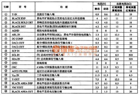
TAl226NA is a transient state of luminance improvement integrated circuit,and it is applied to various large-screen colour TVs to improve the transient state of luminance.Its function and data of pins of the integrated circuit are shown as chart 1.
(View)
View full Circuit Diagram | Comments | Reading(560)
Circuit Categories
power supply circuit
Amplifier Circuit
Basic Circuit
LED and Light Circuit
Sensor Circuit
Signal Processing
Electrical Equipment Circuit
Control Circuit
Remote Control Circuit
A/D-D/A Converter Circuit
Audio Circuit
Measuring and Test Circuit
Communication Circuit
Computer-Related Circuit
555 Circuit
Automotive Circuit
Repairing Circuit