
Index 50
Voice switches ( for beginners making circuit diagram )
Published:2012/11/5 20:41:00 Author:Ecco | Keyword: Voice switches , beginners making
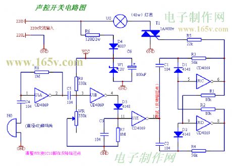
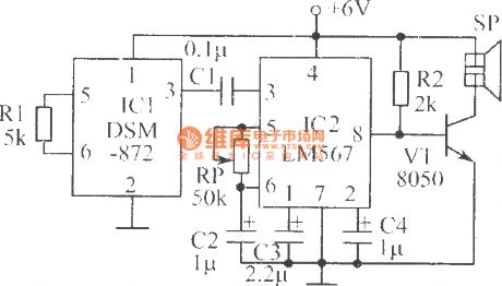
After the installation is complete, there are no errors in the circuit, then it can be used after being adjusted.
(View)
View full Circuit Diagram | Comments | Reading(956)
The roadblocks flashing alarm circuit ( 4 )
Published:2012/11/5 20:48:00 Author:Ecco | Keyword: roadblocks flashing, alarm
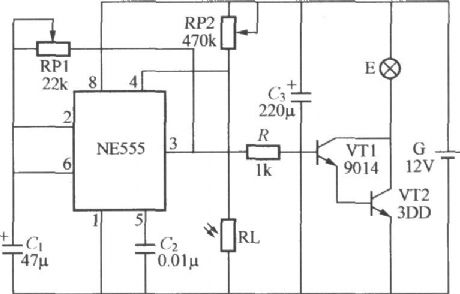
Road blocks flashing warning light using battery is shown in the figure, and it can be used local road facilities without AC power for roadblocks alarm. NE555, RP1 , RP2 , C1 , RL and RL form a a light -controlled self-excited multivibrator. Due to light exposure in daytime, it is in low resistance, NE555 forces reset terminal ④ feet level to be less than 0.4V, and the NE555 is mandatory reset, output end ③ feet is constant low, then VT1 and VT2 are cutoff, warning lights E does not shine. Due to RL has no light exposure in nighttime, it shows a high resistance, then it is divided by RP2 to make ④ feet level increase, when it is greater than 0.4V, you can lift the blockade on the circuit, the circuit is start-up.
(View)
View full Circuit Diagram | Comments | Reading(1196)
Textile machine automatic control circuit
Published:2012/11/4 20:22:00 Author:Ecco | Keyword: Textile machine, automatic control
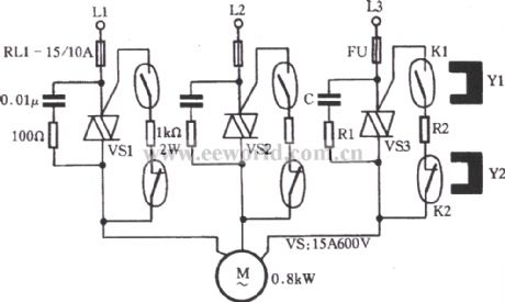
As shown in figure, VS is the triac, R1 and C form the absorption circuit, R2 is the trigger limit measured resistor. K1 is activated dry reed pipe, K2 is the stop dry reed pipe, Y1 , Y2 are the magnets. Sectional phase power L1, L2, L3 is applied to motor M via VS1 ~ VS3. When it is driving, promoting the clutch handle to make Y1 move to the boot position, K1's internal contacts are connected to trigger VS1 ~ VS3 conduction, the motor M is energized; when it is parking, the stop magnet Y2 on clutch handle is near K2, K2's internal normally closed contacts disconnects, trigger circuit is powered down, VS1 ~ VS3 are cut-off, the motor M stops.
(View)
View full Circuit Diagram | Comments | Reading(1474)
Induction heating automatic control circuit
Published:2012/11/4 20:53:00 Author:Ecco | Keyword: Induction heating , automatic control
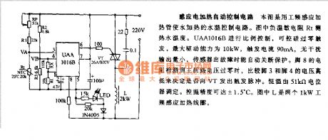
This figure uses labor - frequency induction heating pipe to control the heating water temperature. In Figure, load temperature sensitive resistor Rt is used to measure the temperature of hot water. UAA1016B can make proportional control, SCR is used for zero trigger, the maximum driving capacity is 10kW, trigger current is 90mA, and it can automatically shutdown for protection when sensor occurs failure.
(View)
View full Circuit Diagram | Comments | Reading(3049)
Rapid heating, cooling beverage thermostat machine
Published:2012/11/1 22:51:00 Author:Ecco | Keyword: Rapid heating, cooling beverage , thermostat machine
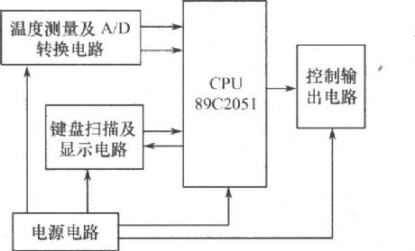

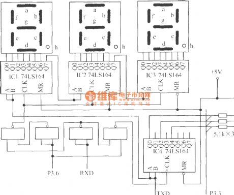
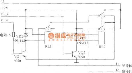
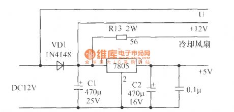

The hardware configuration of the thermostat machine system is composed of temperature measurement and A / D conversion circuit, signal testing and processing circuit, keyboard scan and display circuit, the control output circuit and power supply circuit. The system block diagram is shown below . ( 1 ) Signal testing and processing circuit: the core of the thermostat machine uses AT's cost-effective 8 - bit microcontroller AT89C2051, and it is used to complete the measurement and processing of the data and realize drinks temperature measurement and control function.
(View)
View full Circuit Diagram | Comments | Reading(1471)
The overvoltage protection circuit
Published:2012/10/31 21:21:00 Author:Ecco | Keyword: Overvoltage protection
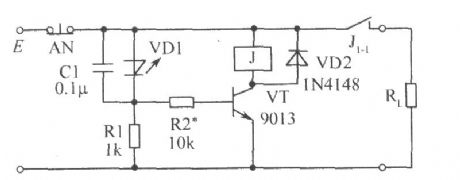
When the external voltage does not exceed the set E voltage Vs, negative resistance light-emitting diode VD1 it cutoff, VT is cutoff because of no base current, relay J does not pull in, and its normally closed contact J1-1 is closed to provide supply for the load RL. Once the external voltage E exceeds the set voltage Vs, VD1 gets conduction, VD1 emitting light to show overvoltage. The the capacitor C1 connected to VD1 in parallel is anti - electromagnetic interference, and it can be selected in the range of 0.01μF ~ 0.1μF.
(View)
View full Circuit Diagram | Comments | Reading(1400)
Open circuit, short circuit anti-theft alarm
Published:2012/10/31 21:00:00 Author:Ecco | Keyword: Open circuit , short circuit , anti-theft alarm
It uses AC driver to make higher light power output by the light emitting diode, the driver circuit is shown in Figure. The two LEDs are connected reversely in parallel, so that the power's positive and negative half-cycle can be dispalyed by a light-emitting diode.
(View)
View full Circuit Diagram | Comments | Reading(1595)
ThinSOT Micropower Buck Regulator
Published:2012/10/30 22:30:00 Author:muriel | Keyword: ThinSOT, Micropower Buck Regulator
View full Circuit Diagram | Comments | Reading(799)
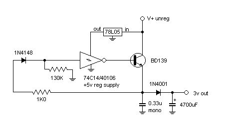
Simple switching regulator (experimental)
Published:2012/10/30 22:28:00 Author:muriel | Keyword: Simple switching, regulator (experimental)
View full Circuit Diagram | Comments | Reading(1329)
5V Buck-Boost (Positive to Negative) Regulator
Published:2012/10/30 22:24:00 Author:muriel | Keyword: 5V , Buck-Boost (Positive to Negative), Regulator
View full Circuit Diagram | Comments | Reading(1524)
5V, 5A Buck (Step Down) Regulator
Published:2012/10/30 22:23:00 Author:muriel | Keyword: 5V, 5A , Buck (Step Down) Regulator
View full Circuit Diagram | Comments | Reading(2096)
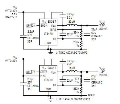
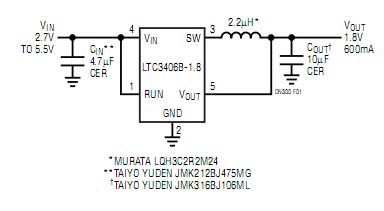
1.8V/600mA Step-Down Regulator Using All Ceramic Capacitors
Published:2012/10/30 22:22:00 Author:muriel | Keyword: 1.8V, 600mA , Step-Down Regulator, Ceramic Capacitors
View full Circuit Diagram | Comments | Reading(786)
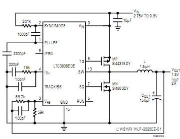
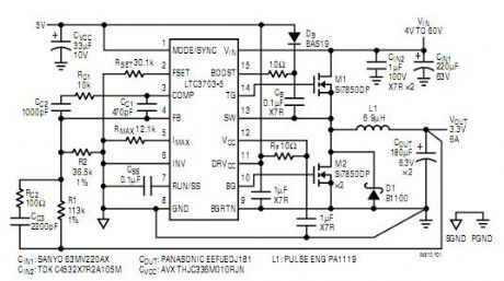
Low EMI Synchronous DC/DC Step-Down Controllers
Published:2012/10/30 22:21:00 Author:muriel | Keyword: Low EMI , Synchronous , DC/DC Step-Down , Controllers
View full Circuit Diagram | Comments | Reading(1862)
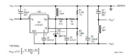
100kHz Low Noise Step-Down Switching Regulator circuits
Published:2012/10/30 22:19:00 Author:muriel | Keyword: 100kHz, Low Noise, Step-Down Switching , Regulator circuits
View full Circuit Diagram | Comments | Reading(791)
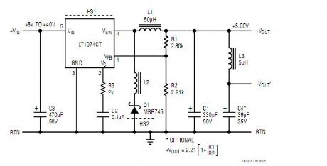
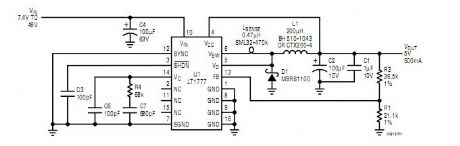
LT1074 switching regulator
Published:2012/10/30 22:16:00 Author:muriel | Keyword: LT1074, switching regulator
View full Circuit Diagram | Comments | Reading(1122)
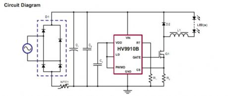
Buck-based LED Drivers Using the HV9910B
Published:2012/10/30 21:44:00 Author:muriel | Keyword: Buck-based LED Drivers, HV9910B
View full Circuit Diagram | Comments | Reading(2886)
Rugged, Fast 60V Synchronous Controller
Published:2012/10/30 21:39:00 Author:muriel | Keyword: Rugged, Fast 60V , Synchronous Controller
View full Circuit Diagram | Comments | Reading(743)
Gas, gas detection alarm circuit using CH217 monolithic gas, gas detection alarm integrated circuit
Published:2012/10/30 21:24:00 Author:Ecco | Keyword: Gas, gas detection , alarm , monolithic gas, alarm integrated circuit
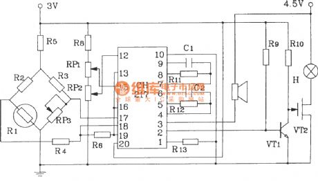
R1 in Figure is agas sensing probe, and its resistance reduces with a linear relationshipto gas concentration increasing, andRP3 is used to adjust the output ofamplifier, R6, R7 are used to draw forecasting and risk baseline signal voltages.
(View)
View full Circuit Diagram | Comments | Reading(1121)
DC motor start circuit controlled by the time relay
Published:2012/10/29 21:50:00 Author:Ecco | Keyword: DC motor, start circuit, controlled , time relay
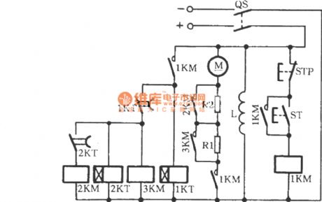
In fact, it is a resistor buck-start DC motor start circuit, but it uses time relay to control the shorted resistor. When the power switch QS is closed, pressing the start button ST can make the DC contactor 1KM be energized, the normally open contact is closed, then the armature loop is connected to R1 , R2. Time relay 1KT also starts at the same time, and its normally open contact 1KT is closed with a delay time, 3KM was energized to make R1 be shorted, then motor M accelerates.
(View)
View full Circuit Diagram | Comments | Reading(1495)
DC motor servo control circuit
Published:2012/10/29 21:56:00 Author:Ecco | Keyword: DC motor , servo control
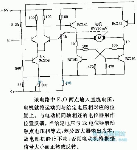
In the circuit, E, O points are input DC voltage, then the motor will be moved to a position corresponding to a given voltage. The potentiometer coaxially connected to motor is used as position feedback. When a given voltage and 1k potentiometer wiper contact voltage are equal, the differential amplifier output is zero, so the motor is stationary; Otherwise, the motor will be transferred or reversal according to the size of the signal.
(View)
View full Circuit Diagram | Comments | Reading(1624)
| Pages:50/312 At 204142434445464748495051525354555657585960Under 20 |
Circuit Categories
power supply circuit
Amplifier Circuit
Basic Circuit
LED and Light Circuit
Sensor Circuit
Signal Processing
Electrical Equipment Circuit
Control Circuit
Remote Control Circuit
A/D-D/A Converter Circuit
Audio Circuit
Measuring and Test Circuit
Communication Circuit
Computer-Related Circuit
555 Circuit
Automotive Circuit
Repairing Circuit