
Index 61
Multifunctional fan control circuit using DZS-01
Published:2012/9/11 22:21:00 Author:Ecco | Keyword: Multifunctional fan, control
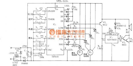
As shown in the circuit, the circuit uses fan control ASIC DZS-01 as the core component, whenthe fan is turned on,it isalso accompanied by beautiful harmonies of nature to give the joy of beauty for people.
(View)
View full Circuit Diagram | Comments | Reading(838)
The series connecting control circuit of electric contact pressure gauge and time relay
Published:2012/9/11 22:04:00 Author:Ecco | Keyword: series connecting , control , electric contact, pressure gauge , time relay
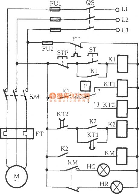
As shown in Figure, the circuit usestwo time relays KT1 , KT2 to connect with thecontactsofelectric contact pressure gauge SP in series. When liquid or gas pressure has not yet reached, it can overcome thetrembling or spark phenomenons because of the SP's incomplete separating andtoucing in the crash time of motor automatic start or stop,and itimprovesthe reliability of circuit.
(View)
View full Circuit Diagram | Comments | Reading(2173)
12-24V Impulse control dimmer
Published:2012/9/11 21:33:00 Author:Ecco | Keyword: 12-24V , Impulse control , dimmer
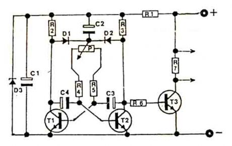
This circuit is intended for use with motors, lamps,heatings etc. Continuously from nearly zero up to maximum capacity (5-95%). Almost lossfree control by means of this impulse control. Nearly total turning moment of motors. The transistior T3 must absolutely be fastened on a heatsink with minimum dimentions of approximate 100x100x5mm. The heatsink has to be fixed insulated as the transistor has a conductive connection between the C-connection and the metal rear side. (View)
View full Circuit Diagram | Comments | Reading(1346)
Auto-Arming Car Alarm circuit
Published:2012/9/11 21:32:00 Author:Ecco | Keyword: Auto-Arming, Car Alarm
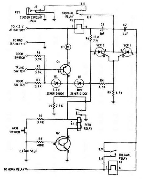
The car alarm here is a simple circuit with basic characteristics that cover all entrances at the car that has switches (doors etc).With one switch (arm-switch) the circuit waits for the sensor-switches to open and to activate it. So the horn with 1 sec pulses will sound imediatelly seconds so the driver can enter in car and disactivate the arming switch. (View)
View full Circuit Diagram | Comments | Reading(1598)
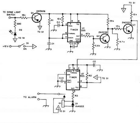
Car alarm circuit using 555 timer
Published:2012/9/11 21:29:00 Author:Ecco | Keyword: Car alarm , 555 timer
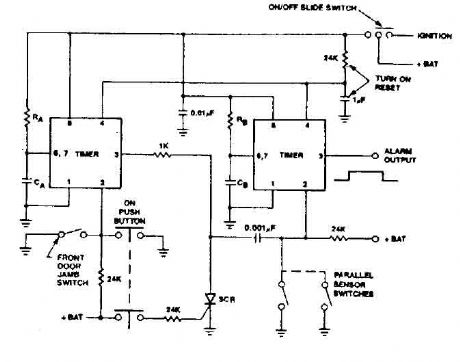
555 timer produces a guaranteed delay, allowing the driver to deactivate the alarm and the elimination of a control switch vulnerable outside. (View)
View full Circuit Diagram | Comments | Reading(2251)
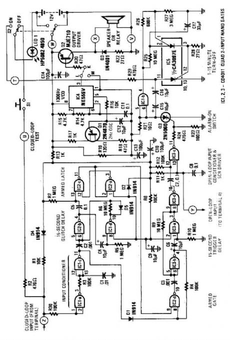
House Alarm Loop Circuit
Published:2012/9/11 21:29:00 Author:Ecco | Keyword: House Alarm , Loop
This circuit offers open and closed loop contacts (switches 1,2,3) that triggers the alarm ON and stays ON for 5 -10 minutes. The trigering delay (entrance/exit) is 27 seconds. This simple alarm circuit Has also a cancel button for reseting the circuit to stand-by mode again. (View)
View full Circuit Diagram | Comments | Reading(1989)
Car Alarm Security Circuit
Published:2012/9/11 21:28:00 Author:Ecco | Keyword: Car Alarm , Security
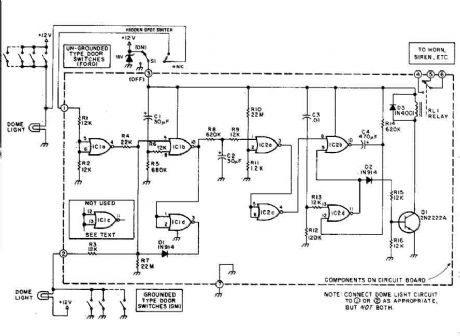
This car alarm circuit offers 18 seconds delay for the entrance and the exit. It sound continually for 6 minutes and automaticaly turns horn off and gets ready for the next trigering. (View)
View full Circuit Diagram | Comments | Reading(1320)
Simple House Alarm circuit
Published:2012/9/11 21:28:00 Author:Ecco | Keyword: Simple , House Alarm
This house alarm circuit has open and closed loop sensor and has self shutdown function. The delay after trigering can be adjusted from 1 minute to 12. The delay before trigering is 13 seconds. Offcourse all this timmings can be change with litle changes to few passive parts. (View)
View full Circuit Diagram | Comments | Reading(1240)
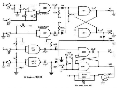
Clever Car alarm circuit
Published:2012/9/11 21:28:00 Author:Ecco | Keyword: Clever , Car alarm
When this car alarm circuit is activated it stays activated for 80 seconds. It has 15 seconds delay for the driver to enter and deactivate. and All timmings can be altered easilly. (View)
View full Circuit Diagram | Comments | Reading(1311)
Automatic level control with NE570
Published:2012/9/11 21:20:00 Author:Ecco | Keyword: Automatic level , control
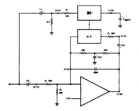
The NE570 can be used to make a high performance compressor FTA, except that the rectifier is connected to the input. This makes gain inversely proportional to the input level so that a drop of 20 dB input level will produce an increase of 20 dB gain. The output remains at a constant level. As shown, the circuit will maintain an output level of ± 1 dB for an input range of + 14 to -43 dB at 1 kHz. (View)
View full Circuit Diagram | Comments | Reading(0)
Car Wiper-Speed Controller
Published:2012/9/11 20:59:00 Author:Ecco | Keyword: Car, Wiper-Speed Controller
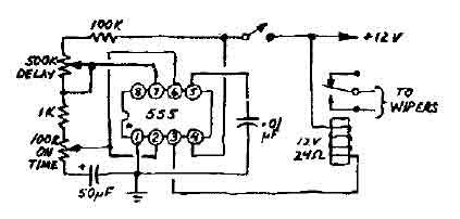
This 12V wiper speed controller circuit uses the 555 timer. And can be fitted to any car. Its one of those very easy and usefull circuits. (View)
View full Circuit Diagram | Comments | Reading(1)
Input pulse width controller circuit
Published:2012/9/11 20:26:00 Author:Ecco | Keyword: Input pulse, width controller
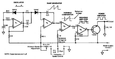
The quad operational amplifier circuit yields full 0 to 100 percent pulse width control. The controller uses an LM3900 requires only a single supply voltage of 4-30 V. The pulse repetition frequency is set by a 1 kHz oscillator amplifier that integrates AI. The oscillator feeds the Az ramp generator, which generates a linear ramp voltage for each pulse oscillator. The ramp signal feeds the inverting input of comparator A3, the control voltage feeds speed non-inverting input. Thus, the output of the comparator is a 1 kHz pulse train, pulse width that changes linearly with control voltage. (View)
View full Circuit Diagram | Comments | Reading(1833)
The photoelectric control trigger circuit
Published:2012/9/11 1:50:00 Author:Ecco | Keyword: photoelectric control , trigger
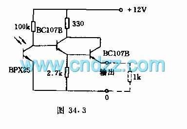
The circuit plays the raster control role of the relay switch. When the light is dimmed, the current output by phototransistor is about 8mA ( supply voltage is 8V ). When the illumination is over 50lx, the circuit flips, the output is 0. The limiting frequecncy of the circuit is 6kHz.
(View)
View full Circuit Diagram | Comments | Reading(948)
Motion Alarm
Published:2012/9/10 21:42:00 Author:Ecco | Keyword: Motion Alarm
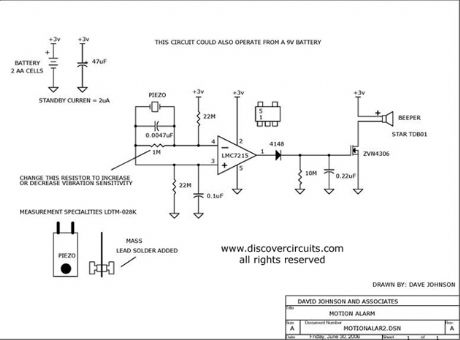
Using a piezoelectric device, this circuit will activate a beeper whenever the circuit is moved. It could be used as an earthquake alarm.
Source: discovercircuits (View)
View full Circuit Diagram | Comments | Reading(1462)
Digital Volume Control
Published:2012/9/10 21:26:00 Author:Ecco | Keyword: Digital Volume, Control
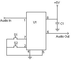
This digital volume control has no pot to wear out and introduces almost no noise in the circuit. Instead, the volume is controlled by pressing UP and DOWN buttons. This simple circuit would be a great touch to any home audio project. (View)
View full Circuit Diagram | Comments | Reading(0)
Overload speaker protection circuit
Published:2012/9/10 20:56:00 Author:Ecco | Keyword: Overload speaker, protection
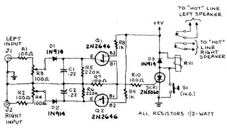
The circuit input is taken from the terminal loudspeaker or amplifier output jacks. If the right channel is large enough to charge C1 to a potential which exceeds the breakdown voltage of the emitter of Ql, a voltage pulse appears in R7. Similarly, if the left channel signal is large enough to charge C2 to a voltage that is greater than the breakdown voltage of the emitter of Q2 , a pulse appears in R7. The pulse triggers in R7 5CRI. A door sensitive SCR (LGT less than 15 RNA or IGT is the gate-trigger current) that locks in a conducting state and energizes Ryl. The action of the relay will interrupt the speaker circuit. and silence follows you must alert on the problem.
Source: discovercircuits (View)
View full Circuit Diagram | Comments | Reading(2085)
Automatic level control with NE570
Published:2012/9/10 20:56:00 Author:Ecco | Keyword: Automatic level , control

The NE570 can be used to make a high performance compressor FTA, except that the rectifier is connected to the input. This makes gain inversely proportional to the input level so that a drop of 20 dB input level will produce an increase of 20 dB gain. The output remains at a constant level. As shown, the circuit will maintain an output level of ± 1 dB for an input range of + 14 to -43 dB at 1 kHz.
Source: discovercircuits (View)
View full Circuit Diagram | Comments | Reading(2196)
Anti - robbery alarm RCM1A/RCM1B transceiver module
Published:2012/9/10 1:03:00 Author:Ecco | Keyword: Anti - robbery , alarm , transceiver module
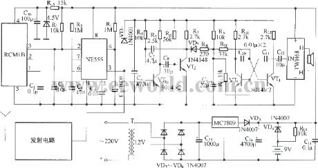
The circuit consists of two parts of a tiny radio transmitter and receiver control alarm. The transmitter is supplied by button battery, and it is compact and easy to carry. Once the accident happens, pressing the transmitter button, the receiver will send a very loud alarm sound. The transmitter circuit inlcudes transmitter module RCM1A, button batteries and launch button; wireless receiver alarm circuit is composed of receiver module RCM1B, monostable multivibrator, composite oscillator circuit, audio booster, high-loudness speaker, power supply circuit and other components.
(View)
View full Circuit Diagram | Comments | Reading(1269)
Voice control flowing Lantern circuit 5G167 with many famous songs
Published:2012/9/10 1:11:00 Author:Ecco | Keyword: Voice control, flowing Lantern , many famous songs
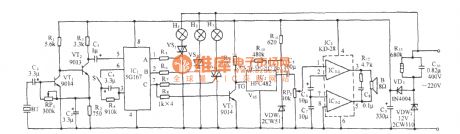
As shown in the diagram, the circuit consists of acoustic/electric sensor, audio amplifier, ring count pulse distribution/driver circuit, thyristor-controlled circuit, music sound circuit, audio amplifier circuit and AC buck rectifier circuit. IC1 uses 5G167 which is used for ring count pulse distribution/driver integrated circuit to rotate the Flash recorder box, it contains signal rectifier amplifier, voltage-controlled oscillator and 3-bit ring sequential counter and 3-drain output circuit and so on.
(View)
View full Circuit Diagram | Comments | Reading(1356)
Voice-control bi-directional flowing water lantern circuit with seashore (5G167)
Published:2012/9/10 1:20:00 Author:Ecco | Keyword: Voice-control, bi-directional , flowing water lantern , seashore
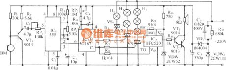
As shown in the diagram, the circuit consists of voice control circuit, monostable trigger, ring count pulse distribution circuit/drive circuit, thyristor trigger control circuit, wave sound audible circuit and AC buck rectifier circuit, it can make three-way Lantern strings auto reverse in both directions, accompanied by the waves beating the shore or the nature sound from mountain and stone.
(View)
View full Circuit Diagram | Comments | Reading(945)
| Pages:61/312 At 206162636465666768697071727374757677787980Under 20 |
Circuit Categories
power supply circuit
Amplifier Circuit
Basic Circuit
LED and Light Circuit
Sensor Circuit
Signal Processing
Electrical Equipment Circuit
Control Circuit
Remote Control Circuit
A/D-D/A Converter Circuit
Audio Circuit
Measuring and Test Circuit
Communication Circuit
Computer-Related Circuit
555 Circuit
Automotive Circuit
Repairing Circuit