
Index 77
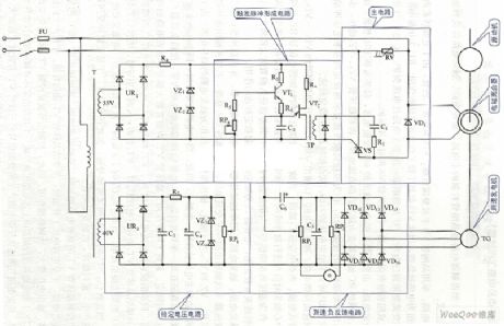
Electromagnetism speed measurement control circuit diagram
Published:2011/9/7 4:29:00 Author:Vicky | Keyword: Electromagnetism speed measurement control circuit
Electromagnetism speed measurement control circuit diagram (View)
View full Circuit Diagram | Comments | Reading(1275)
Control and driving circuit diagram of three-phase DC motor in Y connection
Published:2011/9/6 22:52:00 Author:Vicky | Keyword: control and driving circuit, three-phase DC motor, Y connection
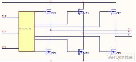
In this circuit, the three-phase winding of the motoris in Y connection. If one is conducted by another, when power diode VF1 and VF2 are conducted, the current flows to A phase winding, and then back to the power supply by C phase winging after flowing through VF2. If the torque generated by the current which flows to the windings is positive, then the torque generated by windings is negative. When the motors turnfor60 degrees, VF2 andVF3 are conducted instead of VF1 and VF2. Meanwhile, the current flows to B phase winding from VF3, and then back to the power supply by C phase winding after flowing through VF2. (View)
View full Circuit Diagram | Comments | Reading(1347)
Bi-directional speed-adjusting motor driver circuit diagram
Published:2011/9/7 9:27:00 Author:Vicky | Keyword: bi-directional, speed-adjusting, motor driver circuit
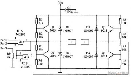
Output and level conversion
Output signal line is introduced by Port. Pin Port1 is the input end of motor direction signal, pin port2 is the PWN signal input end, and pin port3 is the grounding line. Attention that pin port3 is grounded and connected with a 2kΩ resistance. When the driver panel and monolithic provides power respectively, the resistance can provide the backflow passageway for signal circuit. When the driver and monolithic together use a same group of power, the resistance can prevent high current from flowing to the monolithic mainboard ground wire along the line which will lead to interference. Or, it is equivalent to separate the ground wire of the friver panel and the ground wire of monolithic, and to realize “one-point earth fault”. Capacitance C1 prevents the voltage from going down suddenly which is caused by the sudden start-up of the motor. (View)
View full Circuit Diagram | Comments | Reading(1322)
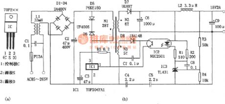
Switch Power Made With Three-terminal PWM Switching Power Supply IC
Published:2011/9/6 6:44:00 Author:Felicity | Keyword: Switch Power, Three-terminal PWM, Switching Power Supply IC
View full Circuit Diagram | Comments | Reading(5035)
Low-power Miniature Switching Power Supply Made With WS157 Or WS106
Published:2011/9/6 6:48:00 Author:Felicity | Keyword: Low-power, Miniature, Switching Power Supply

View full Circuit Diagram | Comments | Reading(1194)
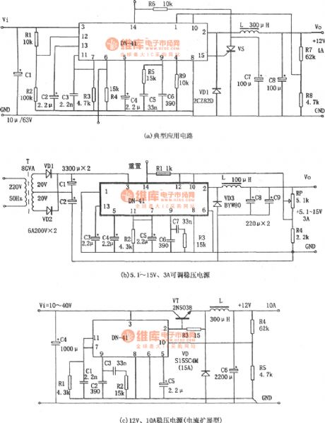
High Current Switching Regulator Made Of DN-41
Published:2011/9/6 6:52:00 Author:Felicity | Keyword: High Current, Switching Regulator
View full Circuit Diagram | Comments | Reading(768)
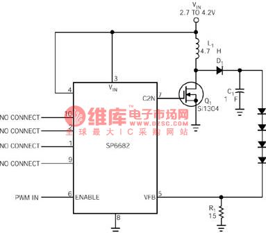
White LED Driver with High Efficiency
Published:2011/8/11 8:17:00 Author:Sue | Keyword: White, LED Driver, High Efficiency
View full Circuit Diagram | Comments | Reading(1026)
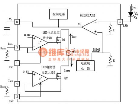
Heavy Current LED Driver LTC3454
Published:2011/8/12 6:42:00 Author:Sue | Keyword: Heavy Current, LED, Driver
View full Circuit Diagram | Comments | Reading(883)
DC-AC conversion circuit control circuit diagram
Published:2011/9/5 4:08:00 Author:Lucas | Keyword: DC-AC conversion, control circuit
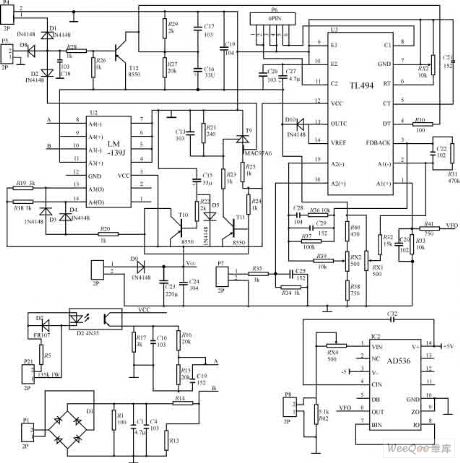
In the figure, the TL494 is used as the core to form the PWM driver and protection circuit, and the changing frequency is 50kHz. 115V output voltage is sent to P8 after stepping-down and isolating, then it is sent to TL494 error amplifier A1 after getting RMS by passing AD536, and it is used as the system's closed-loop voltage control. The current of push-pull inverter circuit is sent to control panel to do signal processing by P7 after passing current transformer sampler, then it is sent to the TL494 error amplifier A2 as the current-loop control system. TL494 outputs driver signal is amplified by passing P6, then it is sent to the main board.
(View)
View full Circuit Diagram | Comments | Reading(3586)
Flower nursery water shortage automatic irrigation control and voice alarm circuit
Published:2011/9/5 21:19:00 Author:TaoXi | Keyword: Flower nursery, water shortage, automatic irrigation, control, voice alarm circuit
View full Circuit Diagram | Comments | Reading(1095)
Photosensitive tracking control circuit
Published:2011/9/6 1:42:00 Author:TaoXi | Keyword: Photosensitive tracking, control circuit
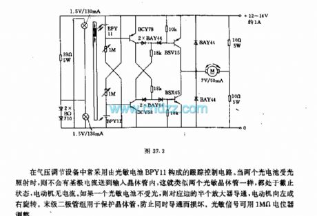
The atmospheric pressure regulating equipments always use the tracking control circuit which is composed of the photosensitive battery BPY11. When both of the two photosensitive batteries are irradiated by the light, there is no base current in the input transistor, they are similar to two phototransistors which are in the cut-off state, the electric motor has no current. If a photosensitive cell is not irradiated by the light, the corresponding edge half-amplifier will conduct, the electric motor turns left or right. The last stage diode group can be used to protect the transistor to prevent the damage. The photosensitive signal can be adjusted by the 10MΩ potentiometer.
(View)
View full Circuit Diagram | Comments | Reading(818)
Light control type electric fan natural wind simulation and music vocal accompaniment control circuit (CD4022)
Published:2011/9/6 2:13:00 Author:TaoXi | Keyword: Light control type, electric fan, natural wind, simulation, music, vocal accompaniment, control circuit
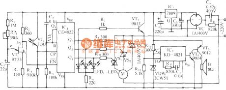
The circuit is as shown in the figure. It is composed of the relaxation oscillator, the light control pulse counting/decoding circuit, the SCR control motor speed control circuit, the music sound circuit and the AC step-down rectifier circuit. Under the strong light, the control circuit starts the fan to blow out the natural wind, and it broadcasts 16 world famous songs.
(View)
View full Circuit Diagram | Comments | Reading(1535)
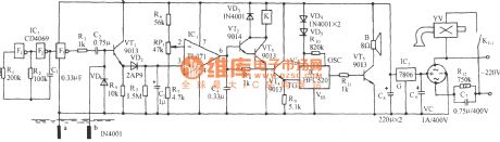
Infrared automatic door controller circuit
Published:2011/9/5 20:48:00 Author:TaoXi | Keyword: Infrared, automatic door, controller circuit
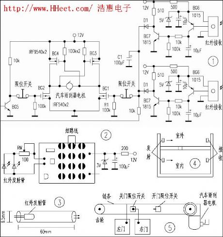
The infrared receiving and motor driver circuit is as shown in figure 1, when there is no one, the infrared receiver receives the infrared beam which is from the other side. You can fix it one the wall by using the 60mm guide tube which can insert the infrared tube exactly (figure 3), the height is appropriate, and it aims at the opposite receiver, so the infrared ray is not easy to interfere another receiver. The installation method is as shown in figure 4. The signal is amplified and filted by BG6, BG7 and CR to output the low level, the BG5 cuts off.
(View)
View full Circuit Diagram | Comments | Reading(1407)
Hualing BCD182 refrigerator control circuit
Published:2011/9/5 20:56:00 Author:TaoXi | Keyword: Hualing, refrigerator, control circuit
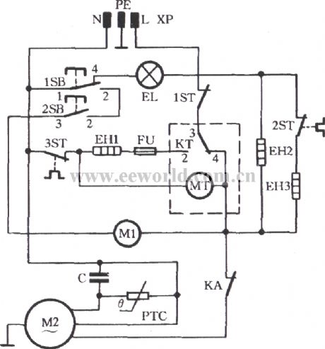
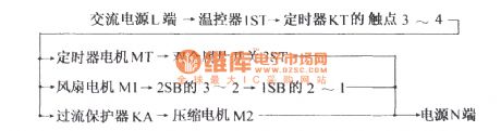
The Hualing BCD182 refrigerator control circuit is as shown in the figure. The button switches 1SB and 2SB are controlled by the refrigerating door and freezer dorr of the refrigerator respectively. When the door closes, the button switch closes too; When the door opens, the button switch cuts off. When the power is connected, the timing motor MT, the fan electromotor M1 and the compression motor M2 get power to operate. The refrigerator starts to refrigerate. The current loop is:
(View)
View full Circuit Diagram | Comments | Reading(896)
Haier BC-118 kitchen cold storage refrigerator circuit
Published:2011/9/5 21:23:00 Author:TaoXi | Keyword: Haier, kitchen, cold storage, refrigerator circuit
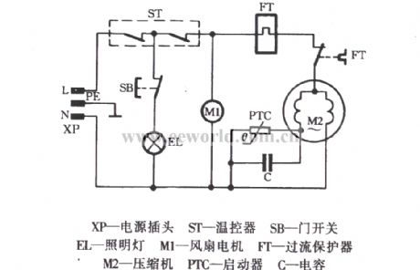
XP-power plug ST-Temperature controller SB-Door switch EL-Light M1-Fan motor FT-over-current protector M2-compressor PTC-Starter
C-capacitor
(View)
View full Circuit Diagram | Comments | Reading(2694)
Over-voltage automatic power off device
Published:2011/9/5 21:32:00 Author:TaoXi | Keyword: Over-voltage, automatic, power off device


The circuit principle is as shown in the figure. The 220V city electricity supplies the stable 12V operating voltage to the switch integrated circuit through the C1, VD1 and DW1, the partial voltage sampling circuit is composed of the VD3, R2 and RP1. When the city electricity voltage is normal, the DW2 can not conduct, the operating voltage of the TWH8778's pin-5 is lower than 1.6V, the relay J will not close, the city electricity supplies power to the socket CZ through J-1; when the city electricity voltage is higher than the normal value, the DW2 is conducted, the electric potential of the TWH8778's pin-5 rises to 1.6V, the IC turns, the pin-3 outputs the high level, the relay closes, the power supply of the electrical appliance is cut off to avoid the damage.
(View)
View full Circuit Diagram | Comments | Reading(973)
Rolling code coding radio transmitting circuit
Published:2011/9/5 21:37:00 Author:TaoXi | Keyword: Rolling code, coding, radio transmitting
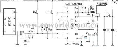
The TDA5100 is designed as the Uhf radio transmitting circuit which is produced by the Siemens company, the internal structure is complex, the function is perfect, the sensitivity is high, the output signal amplitude is wide, the external components are few, the price is cheap, it is the superior performance transmitting circuit.
(View)
View full Circuit Diagram | Comments | Reading(1470)
Insufficient light automatic turn-on bird sound circuit
Published:2011/9/6 1:11:00 Author:TaoXi | Keyword: Insufficient light, automatic turn-on, bird sound circuit

As the figure shows, it is composed of the photoelectric sensor integrated circuit ULN3300, the relay control lighting circuit and the bird sound circuit, the AC step-down rectifier circuit.
(View)
View full Circuit Diagram | Comments | Reading(1268)
Insufficient light cock sound alarm circuit
Published:2011/9/6 1:14:00 Author:TaoXi | Keyword: Insufficient light, cock sound, alarm circuit
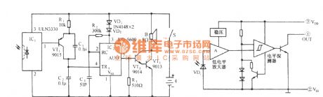
As the figure shows, it is composed of the ULN3330 photoelectric sensor, the cock sound alarm circuit and the audio amplifier.
(View)
View full Circuit Diagram | Comments | Reading(1140)
Gas Annunciator Diagrams
Published:2011/9/6 21:21:00 Author:Vicky | Keyword: Gas Annunciator
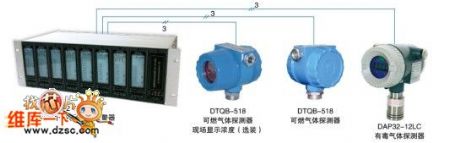
DAP2101-GP1 combustible gas annunciator control system adopts plug-in annunciator and explosion-proof DTQB-518 type (three wire system, 4~20mA) combustible gas transmitter. When there is combustible gas in the air, the transmitter shall send out a proportional 4-20mA signal corresponding to the combustible gas concentration to the annunciator. The annunciator displays the percentage concentration of lower explosion limit. When the value of concentration reaches the pre-set annunciating value, the annunciator sends out sound and light alarming and control system to warning the operating personnel to take measures to guarantee safety in production and avoid explosive accident.
(View)
View full Circuit Diagram | Comments | Reading(739)
| Pages:77/312 At 206162636465666768697071727374757677787980Under 20 |
Circuit Categories
power supply circuit
Amplifier Circuit
Basic Circuit
LED and Light Circuit
Sensor Circuit
Signal Processing
Electrical Equipment Circuit
Control Circuit
Remote Control Circuit
A/D-D/A Converter Circuit
Audio Circuit
Measuring and Test Circuit
Communication Circuit
Computer-Related Circuit
555 Circuit
Automotive Circuit
Repairing Circuit