
Index 74
Numeric control instrument of photoconductive control circuit diagram
Published:2011/8/2 1:09:00 Author:Ecco | Keyword: Numeric control instrument, photoconductive control
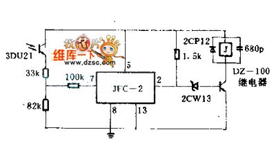
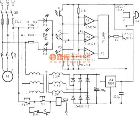
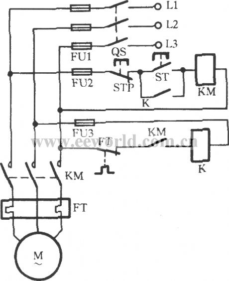
when a arbitrarily warping wire breaks, the light shield held by this warping wire will fall down, simultaneously, the light shield turns back the light that from the 3DU21 photosensitive tube, and the relay in the warping wire will be released, and that will make a parking by controlling its motor.
(View)
View full Circuit Diagram | Comments | Reading(835)
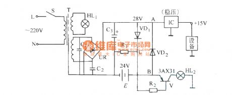
The power failure alarm circuit
Published:2011/9/18 20:56:00 Author:Ecco | Keyword: Power failure , alarm circuit
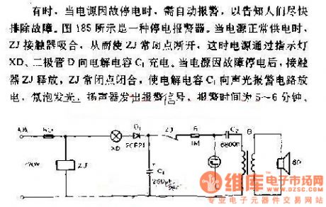
Sometimes, when the power is black out for some reasons, it needs to alarm automatically to inform people overcoming the breakdown as soon as possible. Figure 185 shows a power failure alarm. When power supply works normally, ZJ contactors pull in, so that the ZJ normal closed contact cuts off, then power is charged by the electrolytic capacitor C1 between the lights XD and diode D. When the power is black out for some reasons, ZJ contactors release, so that electrolytic capacitor C1 discharges to the sound and light alarm circuit, neon light bulbs turn on, speakers emit alarm signals, the alarm time is 5 to 6 minutes.
(View)
View full Circuit Diagram | Comments | Reading(979)
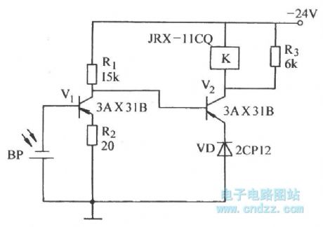
Phototroller circuit
Published:2011/9/12 21:11:00 Author:Ecco | Keyword: phototroller
View full Circuit Diagram | Comments | Reading(726)
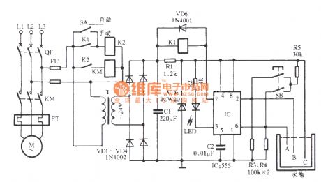
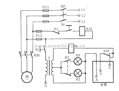
The pump control circuit controlled by time relay
Published:2011/9/12 21:10:00 Author:Ecco | Keyword: pump control , time relay
View full Circuit Diagram | Comments | Reading(1134)
Magic Lantern control circuit (LM3914)
Published:2011/9/12 20:40:00 Author:Ecco | Keyword: Magic Lantern control
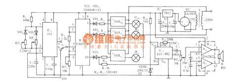
The circuit is shown as the chart. It consists of multivibrator, graphics driver circuit, AC solid-state relay control circuit, music sound circuit, audio amplifier circuit and the AC voltage regulator rectifier circuit. It can produce changing patterns lantern and accompanied by beautiful music. Time-base circuit 555 and R1, RP1, RP2, C1 form a non-steady-state multivibrator, as the VD1, VD2 are added, the charging and discharging circuits are different, and changing the RP2 and RP1 can adjust its charging and discharging loop, which can change the charging and discharging rate.
(View)
View full Circuit Diagram | Comments | Reading(1356)
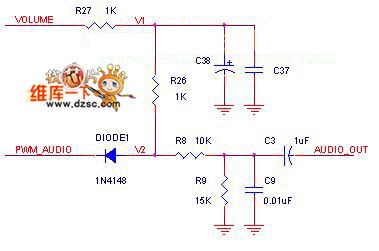
Digital audio volume control circuit diagram
Published:2011/9/9 2:04:00 Author:Ecco | Keyword: Digital audio , volume control
View full Circuit Diagram | Comments | Reading(1576)
Automatic refrigerator protector circuit diagram
Published:2011/9/1 2:03:00 Author:Ecco | Keyword: Automatic refrigerator protector
View full Circuit Diagram | Comments | Reading(2386)
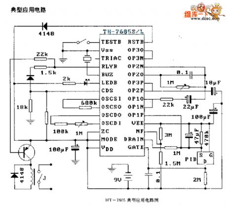
HT-7605 pyroelectric infrared receiver control circuit diagram
Published:2011/9/14 2:58:00 Author:Ecco | Keyword: pyroelectric infrared , receiver control
View full Circuit Diagram | Comments | Reading(1056)
Photoelectric sensor type three-phase protection circuit
Published:2011/9/14 21:58:00 Author:Christina | Keyword: Photoelectric sensor type, three-phase, protection circuit
View full Circuit Diagram | Comments | Reading(2498)
Simple water level control circuit
Published:2011/9/14 21:57:00 Author:Christina | Keyword: Simple, water level, control circuit
View full Circuit Diagram | Comments | Reading(2157)
AC/DC non-contact switching circuit
Published:2011/9/14 21:55:00 Author:Christina | Keyword: AC, DC, non-contact, switching circuit
View full Circuit Diagram | Comments | Reading(837)
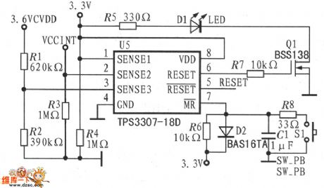
Voltage monitor and reset circuit diagram
Published:2011/9/14 2:04:00 Author:Ecco | Keyword: Voltage monitor , reset
View full Circuit Diagram | Comments | Reading(826)
Simple three-phase electromotor broken phase protection circuit
Published:2011/9/14 21:25:00 Author:Christina | Keyword: Simple, three-phase, electromotor, broken phase protection
View full Circuit Diagram | Comments | Reading(1171)
Household flammable gas leakage automatic ventilation and alarm circuit
Published:2011/9/14 21:37:00 Author:Christina | Keyword: Household, flammable gas, leakage, automatic ventilation, alarm circuit
The circuit is as shown in the figure. It is composed of the gas sensor detection circuit, the amplifier, the relay control exhaust fan circuit, the analog sound circuit and the AC step-down rectifier circuit. It can be used in the family kitchen, the leakage alarm of the flammable gas in the bathroom.
(View)
View full Circuit Diagram | Comments | Reading(1575)
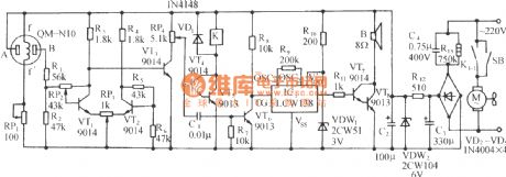
Poultry barn constant temperature control and music sound circuit
Published:2011/9/14 21:31:00 Author:Christina | Keyword: Poultry barn, constant temperature control, music sound
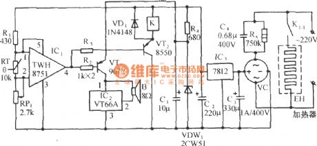
The circuit is as shown in the figure. It is composed of the temperature detection and temperature limit gating switch, the relay control heating circuit, the music circuit, the AC step-down rectifier circuit. It can be used in the poultry hatch, feeding and water temperature control applications.
(View)
View full Circuit Diagram | Comments | Reading(720)
Switch off isolation circuit diagram
Published:2011/9/14 23:48:00 Author:Sophia | Keyword: Switch off, Isolation
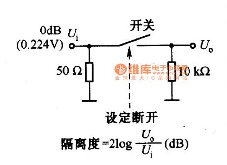
Conversion signal switches include mechanical switches, relays, analog switches. The frequency of the signal must be paid attention to when choosing these switches, not only the signal frequency through the switch need to be paid attention to when the switch is turned on, but also the signal via the switch leakage frequency need to be paid attention to when the switch is off, that is the isolation when switch is off. Figure is a the measurement circuit of the isolation when variety of small-signal switches are off. When frequency is 1MHZ, for mechanical switches and analog switches, the isolation is about 30dB, for the relay, it is about 25dB. Due to the impact of the switch construction and distributed capacitance within the switch, the isolation will become low. Therefore, the circuit construction can be considered to improved. high-frequency signal dedicated switch with enough isolation can be adopted. (View)
View full Circuit Diagram | Comments | Reading(1164)
LM139/239/339 Low power consumption low disorders voltage comparator circuit
Published:2011/9/13 20:29:00 Author:Fiona | Keyword: Low power consumption, low disorders, voltage comparator
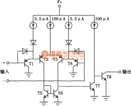
LM139/239/339are kind of excellent performance, wide application of the voltage comparator.Its consumption is small,offset current is low and bias current is small,it can be single power supply,the output end is compatible with a variety of logic circuit (TTL / DTL / ECL / MOS / CMOS),each package has four independent comparators.Its interior circuit and the same phase voltage comparator with lag function are shown above.
(View)
View full Circuit Diagram | Comments | Reading(1895)
16 bit D/A Commutator
Published:2011/9/14 10:12:00 Author:Joyce | Keyword: 6 bit, D/A , Commutator
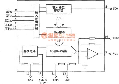
DAC714 is a 16 bit D/A commutator with high-precision and fast serial input. Its conversion time is less than 60 ns. Also it can be reset. The linearity error is small (< ± 4 LSB). There are many choices for the power supply (±12 V and± 15V) with high precision (precision reference power of 10 V is installed within).The internal circuit is as shown in the figure. (View)
View full Circuit Diagram | Comments | Reading(685)
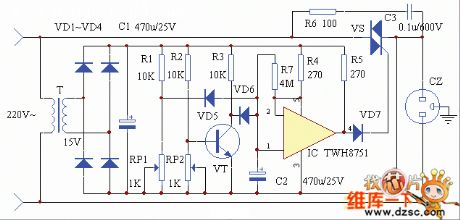
incandescent light life extension switch circuit
Published:2011/9/12 22:02:00 Author:John | Keyword: incandescent light, extension switch
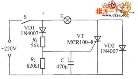
Incandescent light’s filament is with large thermal resistance and very small cold resistance. So at the moment of opening light, the impact current flowing through the filament is very large. It can be very easy to make the filament burn within damages. Life extension’s switch can be a good solution to this problem, just as shown in the figure.It can effectively extend lamp’s life greatly. When switch S is connected, the voltage across the capacitor can not change suddenly and the voltage across C is zero. The thyristor VT deadlines without triggering voltage. At this moment, the current flowing through the bulb E is the half-wave current rectified by VD2. The light bulb is pre-heated with darkness and the inrush current is very small.
(View)
View full Circuit Diagram | Comments | Reading(1566)
Theory of Land Cruiser 70 Light Cross-country Car Engine Control and its Ignition
Published:2011/9/12 23:52:00 Author:Zoey | Keyword: Land Cruiser, 70 Light Cross-country Car, Engine Control, Ignition
Figure: Theory of Land Cruiser 70 Light Cross-country Car Engine Control, Ignition (22R-E,22R motor)
13 a fuel injector; 14 an electronic fuel injection systems (EFI) Main relay; 15 - fuel pump relay; 16 a fuel pump motor; 17 a knock sensor; 18 an oxygen sensor; 19 an air flow meter; 20 a fault detection socket; 21 - valve fuel pressure increases; 22 an air injection system valve; 23 an engine electronic control unit (ECU); 24 an engine warning light detection; 25 a coolant temperature sensor; 26 a throttle position sensor; 27 point fire coil; 28 point fire module (electronic components); 29 a distributor (22R-E engine); 30 A contact-type distributor (22R engine); 31,40 a - anti-interference filter; 92 a speed sensor; 113 a brake light switch; 69 a combination of dashboard 6C terminal (tachometer); 69-7D - four-wheel drive indicator light (View)
View full Circuit Diagram | Comments | Reading(861)
| Pages:74/312 At 206162636465666768697071727374757677787980Under 20 |
Circuit Categories
power supply circuit
Amplifier Circuit
Basic Circuit
LED and Light Circuit
Sensor Circuit
Signal Processing
Electrical Equipment Circuit
Control Circuit
Remote Control Circuit
A/D-D/A Converter Circuit
Audio Circuit
Measuring and Test Circuit
Communication Circuit
Computer-Related Circuit
555 Circuit
Automotive Circuit
Repairing Circuit