
Index 68
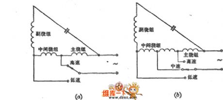
L1 winding tap speed regulation circuit
Published:2011/10/27 22:43:00 Author:May | Keyword: L1 winding tap , speed regulation
View full Circuit Diagram | Comments | Reading(602)
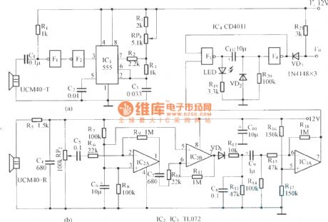
Morning and evening light-operated switch circuit
Published:2011/11/23 21:07:00 Author:May | Keyword: light-operated switch, Morning and evening
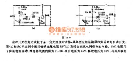
This kind of switch acts when it is above or below a cetrtain illumination, andits typical application is morming and evening street light auto switch. Diagram (a) and (b) show two circuits which adopt cadmium iodide photoresistor RPY20 directly supplied by AC electric fence. 1KΩ resistor isused to reducecurrent pulse. Relay coil 's essential resistance is 21.8Ω, and the pull-in voltage is 45V, release voltage is 18V. The capacitor connected with it in parallel makes up the RC with time constant in 0.1s, in order to minish the pulse DC voltage output by short-lived light flash and smoothness diode and prevent relay tremble, the relay touch point in diagram (a) circuit is normal closed. During the day,theillumination intensity is strong ( >31~45lx), thephotoresistance resistance is small, relay acts, andtouch point isopen, lamp goes out. At night, when illumination intensity is weak (<8.5~11lx) , on the contrary, the relay touch point in diagram (b) is normally open, its work is opposite from diagram (a). (View)
View full Circuit Diagram | Comments | Reading(1223)
Long-time turnoff delay circuit
Published:2011/11/10 1:24:00 Author:May | Keyword: Long-time, turnoff delay
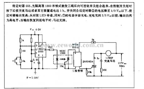
The timer 555, optoisolator 1300 and bridge trigger three-terminal bidirectional thyristor switch is combined in the circuit, after control switch ispressed with short time,it will makeAC motor or other devicebreakover with 1h. After switch isclosed, timer 2 's voltage drops to under 1/3Vcc tomake timer output rise, thereby LED isbreakover. At the same time, 7 capacitor starts charging, befor it is charged to 2/3Vcc, the output is still in high level; when output recovers to low level, the motor turns off.
(View)
View full Circuit Diagram | Comments | Reading(1158)
Floodlight energy-saving controller circuit composed of CD4069
Published:2011/11/4 1:28:00 Author:May | Keyword: Floodlight energy-saving controller
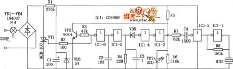
Floodlight energy-saving controller can make floodlight closed during the day, when someone moving generates sound at night, floodlight it automatically works,ao it has the energy-saving and practical features, and it is suitable for stair aisle illuminator's control.
(View)
View full Circuit Diagram | Comments | Reading(1068)
Advertisement lamp automatic control circuit (555、CD4060)
Published:2011/11/4 1:27:00 Author:May | Keyword: Advertisement lamp automatic control
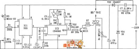
Most advertising lights have good publicity function only before 12 o 'clock at night, after midnight, pedestrian isscarce,then itloses theadvertising significance. This advertisement lamp automatic control circuit can connect power of advertising light brand automaticlly in the evening, at the same it starts timing, after 4 ~ 6 hours at midnight, it automatic cuts off power, so it realizes the automatic control and energy-saving purpose. The diagram is advertising light automatic control circuit, andit consists of power transformation, optical and timed components.
(View)
View full Circuit Diagram | Comments | Reading(1824)
Advertisement lamp automatic control circuit composed of 555、CD4060
Published:2011/4/23 9:07:00 Author:May | Keyword: Advertisement lamp automatic control
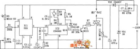
Most city advertising light have good publicity function only before night 12 o 'clock, after midnight, pedestrian scarce, also lost advertising significance. This advertisement lamp automatic control circuit can connect power of advertising light brand automaticlly in the evening when the day was black, at the same time it starts timing, after 4 ~ 6 hours at midnight automatic cut-off power, so as to realize the automatic control and energy-saving purpose. As shown in the diagram is advertising light automatic control circuit, it consists of power transformation, optical and timed components.
(View)
View full Circuit Diagram | Comments | Reading(1583)
Touching dimmer circuit composed of S7232
Published:2011/11/3 21:37:00 Author:May | Keyword: Touching dimmer
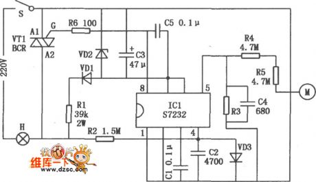
Touching dimmer circuit is shown in the following diagram. It uses finger touch control pieceto realize turning on, off or stepless adjustment for incandescent light. It is used in the dimmer of filament lamp, small AC motor's stepless speed regulation.
(View)
View full Circuit Diagram | Comments | Reading(2710)
Car light flashing circuit composed of 555, CD4017B
Published:2011/11/3 21:31:00 Author:May | Keyword: Car light flashing, 555
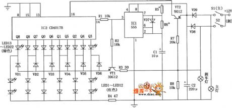
Car light flashing circuit mainly consists of red, green lights. When it emits light,red light islighten from middle to end, and green light jumps from end to middle. When car drives normally, red light and green light arelighten according to program order. When it is braking, all green lights die out, but all red light are lighten. Car light flashing circuit is shown in the diagram.
(View)
View full Circuit Diagram | Comments | Reading(2833)
Circular lights control circuit (555, C180)
Published:2011/11/4 1:03:00 Author:May | Keyword: Circular lights control, 555
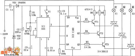
Circular lights control circuit is shown in the diagram. The circuit contains three Gezer lights E1, E2 and E3, it generates red light, green light and blue light. According to the principle of mixed color, red, green and blue can be mixed in different combinations, which includes seven color lamplight of red, green, blue, yellow, purple, green and white. Seven color light flashes in cycle , and the circulation speed is adjustable, and thecircuit has fixed color switch, which can fixed display needed colors.
(View)
View full Circuit Diagram | Comments | Reading(1181)
Electronic touch dimmer circuit composed of CD4028
Published:2011/11/9 21:47:00 Author:May | Keyword: Electronic touch dimmer
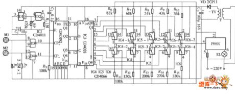
The diagram is touch dimmer which uses a kind of parameters of solid state relays (PSSR) as main control component, and it is not normally used bidirectional thyristor. The light adjusting process uses touching method,and itis convenient, and the circuit is shown in the diagram. This circuit consists of touch control signal input circuit, stepper control pulse generator, pulse / down counter, pulse signal decoding distributor, ten control parameters of solid-state switches and relays, etc.
(View)
View full Circuit Diagram | Comments | Reading(3024)
Thirty bits falling water lamp digital control circuit
Published:2011/11/30 20:39:00 Author:May | Keyword: Thirty bits, falling water lamp, digital control
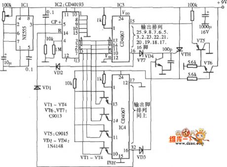
The color lamps controllingcircuit shown in the chart hasthirty outputs, whichcan control thirty lamps todo falling water sports by the external driver circuit, and it can beused as large size decoration variegated lamp controller, and the circuit is shown in the diagram. The diagram consists of control impulse generator, control impulse distributor and variegated lamp control output circuit.
(View)
View full Circuit Diagram | Comments | Reading(1183)
Four-sound circulating burglar alarm circuit
Published:2011/10/27 21:52:00 Author:May | Keyword: Four-sound circulating, burglar alarm
When field-effect tube VT1 (3DJ6)'s wire is serviceable, it presents cut-off state, andpin 2 of JG (555) setting trigger end presents high level, and 555 is in reset state, namely pin 3 presents low level ( it islower than 0.4V). 555 and R1, C1 form the monostable trigger circuit. Whenpeople touch wire, human body's induction signal is amplified byVT1,set byIC1, thenits pin 3 turns to high level ( about 6V) to offer work voltage to IC2, VT2, etc.
When the wire is broken, IC1 is always in setting state, IC2, IC6, etc get electricity to be in continuous alarm state, and it send sout four- sound circulating alarm sound. IC2 and R2, R3, C4, etc make up ultra-low frequency multivibrator, and the oscillation or not depends on thepower supply. Its oscillation frequency f=1.44/(R2+2R3)C4. (View)
View full Circuit Diagram | Comments | Reading(1013)
HD-3A energy-saving quota three-phase power supply protector circuit
Published:2011/10/27 22:12:00 Author:May | Keyword: Energy-saving quota , three-phase, power supply protector
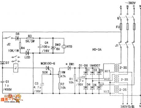
Current transformer H11-3can behomemade. People can choose transformer's iron core which is not less than 2W to wind secondaryfirstly.It usesΦ 0.12 mm varnished wire to wind1,000 turns. The primary uses Φ 1 ~ 4mm plastic wireto wind2 - 3 turns. It also can use current transformer. Finished current transformer induced voltage is quite high.
(View)
View full Circuit Diagram | Comments | Reading(2246)
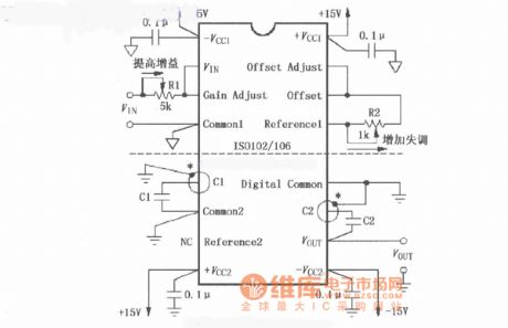
The gain adjustment, detuning regulation and bandwidth control circuit of ISO102/106
Published:2011/8/30 1:39:00 Author:Jessie | Keyword: gain adjustment, detuning regulation , bandwidth control
View full Circuit Diagram | Comments | Reading(792)
Auto voltage monitoring circuit diagram
Published:2011/8/19 2:34:00 Author:Jessie | Keyword: Auto voltage monitoring
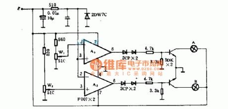
This circuit is applied to supervise if auto power supply voltage12V is normal or not. If the power supply voltageis 12~14.5 V, then it is normal, whenit is lower than 12V or higher than 14.5V,the indicator will be lit up. A(1), A(2) are indicator comparators for adjusting potentiometers W (1), W (2). When thecar's power supply voltage is higherthan 1.45 V, lamp B is on; or it is lower than 12V,lamp A is on;Normal, these two lights are not bright. (View)
View full Circuit Diagram | Comments | Reading(851)
Wireless motorcycle burglar alarm circuit
Published:2011/10/24 2:32:00 Author:May | Keyword: Wireless, motorcycle burglar alarm
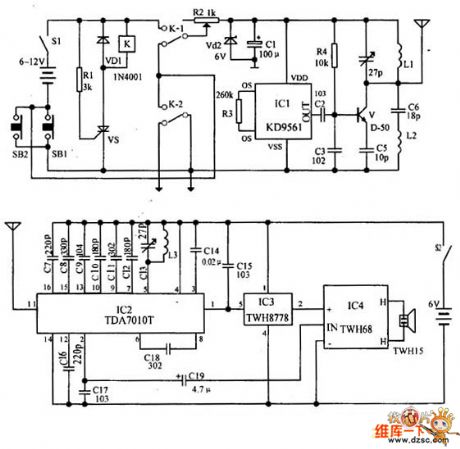
The relay K and SCR VS are used to control the transmitter circuit's power. IC1 forms the alarm signal circuit. And the transistor V and its peripheral components form the radio frequency oscillator circuit to transmit alarm signal. In the waiting state, the switch S1 is connected, and SB1 is disconnected (ie, the front lock is locked), K is in the release state, then the alarm transmitter does not work. When the lock is opened (ie SB1 is connected), VS is triggered for conduction, K is pulled in to turn on the transmitter power. SB1 is switched on, K-2's normally open point is self-locking, and only alarm S1 disconnecting can end the alarm at this time. When K acts, its normally closed contact K-l is off.
(View)
View full Circuit Diagram | Comments | Reading(1485)
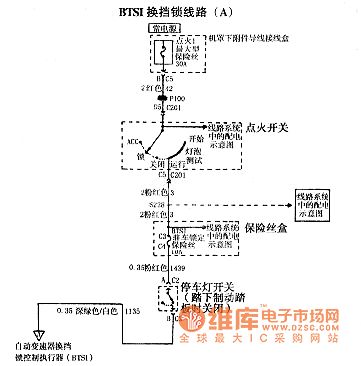
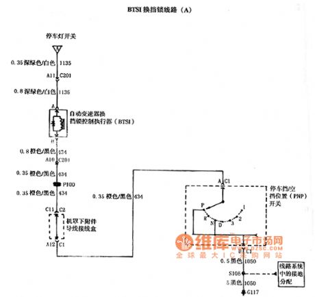
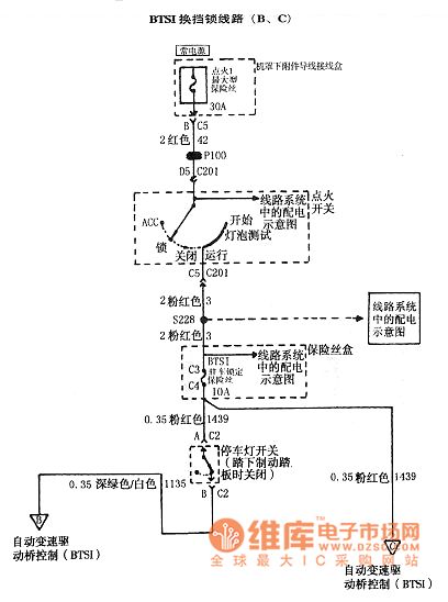
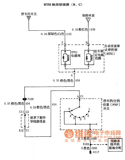
SGM Regal 2.0 L automatic transmission circuit diagram
Published:2011/8/24 2:41:00 Author:Jessie | Keyword: SGM Regal , 2.0 L automatic transmission
View full Circuit Diagram | Comments | Reading(810)
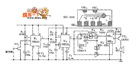
Sound control color light circuit 555, KD-5602 with twitter
Published:2011/12/8 1:04:00 Author:Ecco | Keyword: 555, Sound control, color light , twitter

The circuit is shown as the chart. It consists of acoustic / electric sensors , trigger timing circuit , thyristor trigger control circuit , twitter circuit andAC buck rectifier circuit.
(View)
View full Circuit Diagram | Comments | Reading(1111)
Sound control color light circuit with twitter( 555, KD-5602 )
Published:2011/12/8 1:05:00 Author:Ecco | Keyword: 555, Sound control, color light, twitter
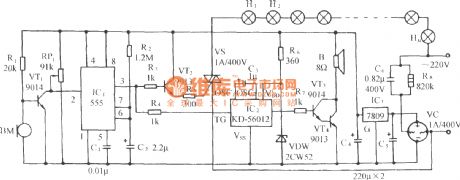
The circuit is shown as the chart. It consists of acoustic / electric sensors , trigger timing circuit , thyristor trigger control circuit , twitter circuit andAC buck rectifier circuit.
(View)
View full Circuit Diagram | Comments | Reading(1124)
Ultrasonic guard against theft alarm detector
Published:2011/9/15 2:21:00 Author:Rebekka | Keyword: Ultrasonic guard against theft alarm
View full Circuit Diagram | Comments | Reading(1914)
| Pages:68/312 At 206162636465666768697071727374757677787980Under 20 |
Circuit Categories
power supply circuit
Amplifier Circuit
Basic Circuit
LED and Light Circuit
Sensor Circuit
Signal Processing
Electrical Equipment Circuit
Control Circuit
Remote Control Circuit
A/D-D/A Converter Circuit
Audio Circuit
Measuring and Test Circuit
Communication Circuit
Computer-Related Circuit
555 Circuit
Automotive Circuit
Repairing Circuit