
Index 80
Servo control circuit of DC motor
Published:2011/8/26 3:11:00 Author:Jessie | Keyword: DC motor, Servo control
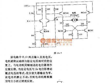
In this circuit, accessing dc current to E, O will make the motor move to the position which corresponding withthe given voltage. When given voltageis equal toearn potentiometer sliding contacts voltage, differential amplifiers output 0, so motor stops; Or motor will film or reverse according to the signal size.
(View)
View full Circuit Diagram | Comments | Reading(1664)
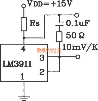
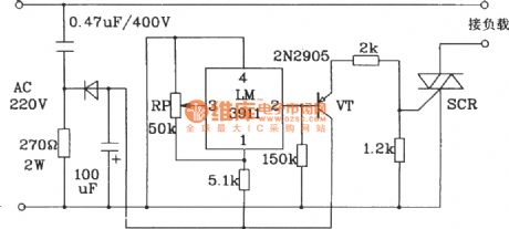
Capacitive load temperature measurement circuit composed of LM3911 monolithic temperature control integrated circuit
Published:2011/8/26 2:48:00 Author:Jessie | Keyword: Capacitive load, temperature measurement, monolithic temperature control
View full Circuit Diagram | Comments | Reading(800)
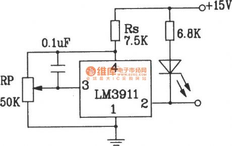
Temperature overheat detection alarm circuit composed of LM3911 monolithic temperature control integrated circuit
Published:2011/8/19 2:57:00 Author:Jessie | Keyword: Temperature overheat detection alarm, monolithic temperature control

View full Circuit Diagram | Comments | Reading(1115)
Plus benchmark power supply temperature detection circuit composed of LM3911
Published:2011/8/19 2:51:00 Author:Jessie | Keyword: Plus benchmark power supply, temperature detection, monolithic temperature control
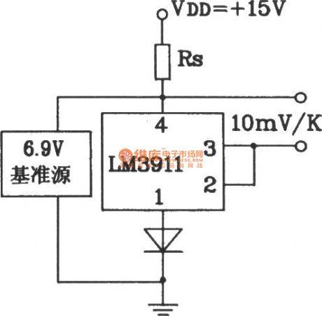
Plus benchmark power supply temperature detection circuit composed of LM3911 monolithic temperature control integrated circuit (View)
View full Circuit Diagram | Comments | Reading(800)
Two-supply temperature measurement circuit composed of LM3911 monolithic temperature control integrated circuit
Published:2011/8/19 2:57:00 Author:Jessie | Keyword: Two-supply temperature measurement, monolithic temperature control
View full Circuit Diagram | Comments | Reading(1359)
Start refrigeration equipment temperature control circuit composed of LM3911 monolithic temperature control IC
Published:2011/8/22 3:30:00 Author:Jessie | Keyword: Start refrigeration equipment , temperature control circuit, monolithic temperature control IC
View full Circuit Diagram | Comments | Reading(1076)
Temperature overrun automatic adjusting socket circuit using MAX6502 temperature switching IC
Published:2011/8/26 1:31:00 Author:Jessie | Keyword: Temperature overrun , automatic adjusting socket, temperature switching IC
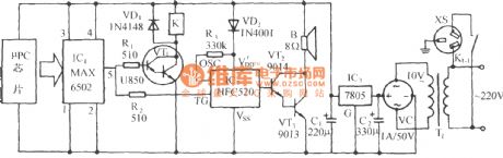
The circuit is shown as the chart, it is composed of the temperature monitoring switch, relay control circuit, language circuit, audio power amplifier circuit and AC step-down rectifier circuit, etc. When the monitored objects or the body's temperature is over the set temperature, socket XS gets electricity, and the ventilation or temperature facilities that insert on it will operate. Meanwhile, sound circuit voice is triggered to emit sound and remind people to notice temeperature changes. MAX6502 is the temperature switch product produced by MAXIM, and its internal functional block diagram is the same with the MAX6501, but its output stage is the push-pull stage, its functional block diagram is shown as the chart.
(View)
View full Circuit Diagram | Comments | Reading(969)
Series-excited motor conditioning speed circuit with two-way trigger tube
Published:2011/8/26 2:00:00 Author:Jessie | Keyword: Series-excited motor, two-way trigger tube
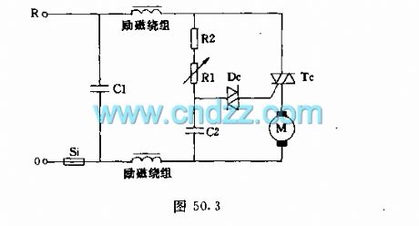
When Capacitor voltageis isover two-way trigger tube Dc turning voltage, the bidirectional thyristor will be connected. Change potentiometer R1's value can control the angle of thyristor, then change the speed of motor. Resistors R2 + R1 can be chosen several hundred kΩ, and Capacitor C is about 0.1μF.
(View)
View full Circuit Diagram | Comments | Reading(868)
On-off temperature control circuit with Integrated flip-flop 5B
Published:2011/8/26 1:59:00 Author:Jessie | Keyword: temperature control circuit, integrated flip-flop

These three circuits are supplied by AC 220V voltage, and the given temperature range is 5 ℃ ~ 30 ℃, and it uses integrated trigger TDA1024 and Triacs BT139,and the heating power is 2KW.
Room temperature (actual temperature) is measured by the thermistor, which is connected in a branch circuit of the bridge. The potentiometer R can adjust the given stable value. If the actual voltage value of pin 5 exceeds the given threshold voltage of pin 4, then the thyristor gate has no trigger pulse. On the contrary, there is trigger pulse, and the heating resistor RL gets power. In order to make the comparator has the minimum hysteresis, pin 3 is hung up, and the temperature difference is about 0.3K.
(View)
View full Circuit Diagram | Comments | Reading(2178)
Dibit temperature regulation circuit with complementary transistor
Published:2011/8/26 1:44:00 Author:Jessie | Keyword: Dibit temperature regulation , complementary transistors
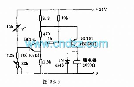
Thegiven temperature and the actual temperature are compared in the bridge road circuit which is composedof theresistor and thermistor. The relationship between input transistor threshold voltage and temperature is negligible, because the threshold voltage of this circuit is only about 5% of the given effective voltage.
The temperature increases while the value of resistor declines, the voltage between NPN transistor base increases, the collector current controls the base of PNP transistor by 1kΩ current limiting resistor, relay suck closes. The hysteresis loop of the circuit is about 0.5%.
(View)
View full Circuit Diagram | Comments | Reading(1338)
Temperature measurement circuit with silicon heating sensitive elements
Published:2011/8/26 2:48:00 Author:Jessie | Keyword: Temperature measurement, silicon heating sensitive elements
This circuit makes silicon heating sensitive elements as sensor,and it isconnected to the brige road and about 2.5V constant voltage. Operational amplifier V1is used as pulse converter, V2 is used as amplifier. Output voltage is between 0 ~ 5V, and it has 50mV/K scale factor between the range of 0 to 100 ℃. The temperature range endpoint is connected an adjusting circuit. First, adjusting the R9 at 0 ℃, then adjusting R4 at 100 ℃. Measurement error can be restricted in ± 0.2K.
(View)
View full Circuit Diagram | Comments | Reading(702)
Temperature control circuit with SL590
Published:2011/8/26 2:41:00 Author:Jessie | Keyword: temperature control
As shown in figure, it iscomposedof temperature sensor, trigger circuit, relay control circuit, language circuit, audio power amplifier circuit andAC step-down rectifier circuit, etc. Temperature control circuituses SL590,and it copies American AD company's AD590,which is the current type 2-end device.
(View)
View full Circuit Diagram | Comments | Reading(629)
Temperature quantity A/D parallel three states output standard microcomputer interface data bus circuit
Published:2011/8/22 3:31:00 Author:Jessie | Keyword: parallel three states output, standard microcomputer interface data bus
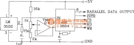
Temperature quantity A/D parallel three states output standard microcomputer interface data bus circuit composed of LM35DZ celsius temperature sensor
(View)
View full Circuit Diagram | Comments | Reading(622)
Temperature control circuit composed of NE555
Published:2011/8/26 2:22:00 Author:Jessie | Keyword: Temperature control
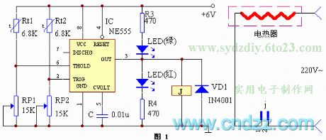
Temperature control circuit is composedof thermistors Rt1, Rt2, NE555 time-based circuit, temperature range adjust resistanceRP1, RP2and control execution organization. Rt1、RP1 are higher limit temperature testing resistors while Rt2、RP2 are lower limit temperature testing resistors. When the temperature drops, potential of pin 2 is below 1/3Vcc, pin 3 outputs high level, J suck closes, LED2 islit, then the circuitbegins heating. When the temperature rises, potential of pin 2 is higher than 1/3Vcc, pin 3 outputs low level, J releases, then it stops heating.
The thermostat has the features of wide applications, high accuracy, low cost, easy to install.
(View)
View full Circuit Diagram | Comments | Reading(2856)
MPY100 Division circuit
Published:2011/8/19 1:41:00 Author:Jessie | Keyword: Division
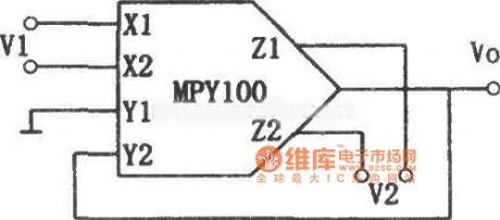
This circuit is composedof multiplier-division integrated circuit MPY100. Input signals are V1, V2, output Vo is: Vo=10V2/V1. This kind of division is composedof multiplieraccessed tofeedback loop of op-amp. V1's input range is -0.2 V to 10V, V2's input range is -10 V to 10V. Circuit's error is bigger, whenV1 is very small. (View)
View full Circuit Diagram | Comments | Reading(783)
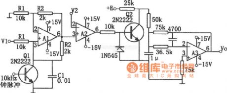
NE555 division circuit
Published:2011/8/19 1:48:00 Author:Jessie | Keyword: division
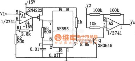
This circuit is composedof voltage - frequency converter and amplitude modulator. Input voltage V1 controls the resistance of mosfet 2N4222by op-ampA1, so can change the oscillation frequency ofastable multivibrator. A2 is amplitude modulator, the input signal outputafter modulated by V2. Set thepinch-off voltage is Vp, if you make (1+R1/R2)=Vp, then the relationship of input and output is Vo=-V2/V1. Request the range of V1 and V2 is 0 ~ 10V. Output Vo is averaged, which can be obtained by the filter and read through the damping type voltmeter. (View)
View full Circuit Diagram | Comments | Reading(942)
Division circuit diagram
Published:2011/8/19 1:50:00 Author:Jessie | Keyword: Division
As shown in figure:
A1 forms Voltage controlled current source, A2is thevoltage comparator, A3 is the active low-pass filter. When time constant R1C1 equals to clock pulse cycle T, the relationship between input and output of circuit is: Vo=-V2E/V1. If make E = 1V, there were Vo=-V2/V1. V1 and V2 are required to bepositive, limited in 10V, the V2 is slightly below V1. Resistance R1, R2 and capacitance C1 required tousethe components with goodtemperature stability. A1 is HA2-2520,A2, A3 are LM101A. (View)
View full Circuit Diagram | Comments | Reading(899)
Cold shutoff temperature control circuit with TWH9205
Published:2011/8/26 2:14:00 Author:Jessie | Keyword: cold shutoff, temperature control
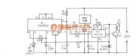
As shown in figure, this circuit is composedofthe zero switch control circuit composedof TW9205 andits peripheral components, SCR drive refrigeration control circuit and sound circuit. The temperature sensor RT in graph uses negative temperature coefficient (NTC) thermal resistor, which is connected to the differential switch amplifier reversed-phase input terminal(pin 9) of TWH9205; Differential switch amplifier phase input terminal(pin 13) and potential clamp fixed end pin 10, 11. Adjust RP1's value so that TWH9205 in set temperature range outputs a low level, and SCR VS in a globe state. When thermistors RT increases to a predetermined value with the temperature, output state of differential switch amplifier is inside the TWH9205, an output terminal of the TWH9205 sents to the high level whenAC powerbecomes zero, SCR VS connected, appliancesget electricity and work.
(View)
View full Circuit Diagram | Comments | Reading(1203)
Ruixing QPL-33 hair repair device circuit diagram
Published:2011/8/19 1:13:00 Author:Jessie | Keyword: Ruixing, hair repair device
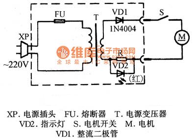
XP-plug; FU-fuse; T-power transformes; VD2-indication light; S-motor switch; M-motor; VD1 rectifier diode (View)
View full Circuit Diagram | Comments | Reading(655)
Division circuit with MC1494 and LM307
Published:2011/8/18 1:10:00 Author:Jessie | Keyword: Division
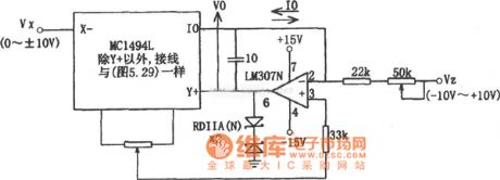
This circuit's output voltage Vo is Vo=10Vz/Vx. The input signal Vx and Vz can be positive and negative, so this circuitis afour quadrant division circuit. Then the voltage-regulator diode in the output end of LM307N is the output voltage clamp diode when the input Vx decreases. (View)
View full Circuit Diagram | Comments | Reading(977)
| Pages:80/312 At 206162636465666768697071727374757677787980Under 20 |
Circuit Categories
power supply circuit
Amplifier Circuit
Basic Circuit
LED and Light Circuit
Sensor Circuit
Signal Processing
Electrical Equipment Circuit
Control Circuit
Remote Control Circuit
A/D-D/A Converter Circuit
Audio Circuit
Measuring and Test Circuit
Communication Circuit
Computer-Related Circuit
555 Circuit
Automotive Circuit
Repairing Circuit