
Radio Circuit
Index
Sound Level Meter Circuit
Published:2012/9/24 4:04:00 Author:muriel | Keyword: Sound, Level Meter
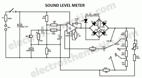
This sound level meter circuit can be used to control the intensity of a sound recording or in a disco. It has 5 measurement domains between 70 and 120 dB; reading accuracy is 0.5 dB. Microphone M1 is used to receive the acoustic signal and is coupled to C1, C2, R1 and R2. This components, together with the microphone’s capacity and with the input impedance of the amplifier form an input filter. The filtered signal goes to operational amplifier IC1 whose sensitivity can be switched with S2 corresponding to the five measuring domains.D1 … D4 diodes rectifies the alternating voltage at the amplifier output and feeds the indicator tool through R9. D5 is used in order to protect the sound level meter indicator against high voltages; it limits the rectifier’s output voltage when the sound level is too high.
On normal conditions the input current is about 2 mA that is why the circuit can be powered with 2 x 9V batteries. S1 switch is used to disconnect the sound level meter device after measurement. The indicator tool should have a graded scale in dB with the maximum value of +10.
Sound Level Meter Schematic
?
4 Responses to “Sound Level Meter Circuit”
(View)
View full Circuit Diagram | Comments | Reading(2376)
Small FM Radio Circuit
Published:2012/9/20 20:56:00 Author:Ecco | Keyword: Small FM Radio
Perhaps this is one of the simplest and smallest FM radio receiver that can receive the FM stations available locally. Its simple design makes it ideal for a pocket sized FM receiver. The output of the receiver drives a head phone.
Tiny FM Radio Receiver Circuit Schematic
The circuit works off a small 4.5 volt battery or two 3.6 volt Lithium button cells.The fm receiver section has two RF transistors T1 and T2 to detect the Frequency Modulated signals. Coil L1 and the trimmer capacito form the tuned tank circuit to tune the receiver to the best FM station with strong signals. The signals are capacitor coupled through C2.
10K preset VR controls the volume to the input of the amplifier. IC1 is the micro power audio amplifier that works between 4.5 to 12 volts DC. The amplified sound can be heard through the low impedance head phone or small Mylar speakers.
FM radio coilCoil is the important part of the FM tuner. It is made up of 18 SWG enameled copper wire. Wind 4 turns on a ball pen to get 0.5 cm inner diameter. Remove the enamel from the tip of the wire and solder tightly in the PCB. Trimmer and coil should be soldered very closely. Adjust the spacing of the coil winding if necessary to get the station clearly. Assemble all the receiver components as close as possible to get better result.
Pinout of BF494 and LM386
?
33 Responses to “Small FM Radio Circuit”
Source: electroschematics.com
(View)
View full Circuit Diagram | Comments | Reading(2895)
FM radio with TDA7000
Published:2012/9/12 20:59:00 Author:Ecco | Keyword: FM radio
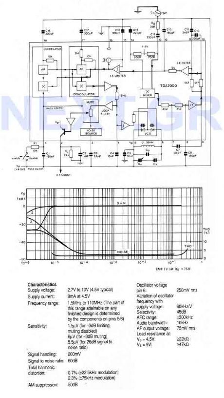
An FM radio on a single chip requiring only a few simple peripheral components. In particular the ship requires only one simple coil and alignment is very easy. The chip includes an RF input stage, mixer, local oscillator, IF amplifier/limiter, phase demodulator, mute detector and mute switch. The output will directly drive a crystal earpiece or could be used with a TBA820M to form a complete portable radio.
Source: NEXT.GR (View)
View full Circuit Diagram | Comments | Reading(2)
Short wave radio for PC
Published:2012/9/12 20:47:00 Author:Ecco | Keyword: Short wave radio, PC
This Cheap circuit will amaze you with its wide range recieving signal between 6 and 17Mhz (49-19meters). Power supply is not necesery, just connect it to your pc, place the antena to your home piping network and voila! (View)
View full Circuit Diagram | Comments | Reading(5927)
Automobile AM radio circuit
Published:2012/8/20 22:29:00 Author:Ecco | Keyword: Automobile, AM radio
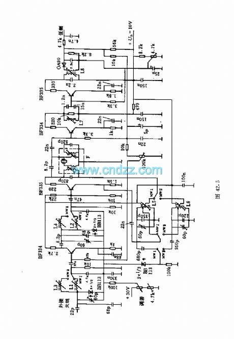
This circuit shows the high and mid part of car radio, and the medium wave band I is 520 ~ 950kHz, Poland II is 900 ~ 1640kHz. Loop tuning uses tunable diode BB113.Main coil data:L1: 122 turns; L2: 122 turns ; L3: 68 turns ; L5: 96 turns ( coupling coil with 7 turns ); L6: 64 turns ( coupling coil with 5 turns) . L1 ~ L6 use 8 × 0.03 copper.L7: 90 turns, 6 × 0.04 copper.L8: 120 turns ( coupling coil with 60 turns ), 8 × 0.03 copper.F: 95 turns ( coupling coil with 5 turns ), 8 × 0.04 copper.
(View)
View full Circuit Diagram | Comments | Reading(2452)
Radio circuit with quartz crystal oscillator
Published:2012/8/21 1:07:00 Author:Ecco | Keyword: Radio , quartz crystal, oscillator
The circuit's frequency can be to 27MHz. Intermediate frequency is 455kHz. In order to increase the receive frequency, it uses the pre-stage of the field effect transistor.
(View)
View full Circuit Diagram | Comments | Reading(1838)
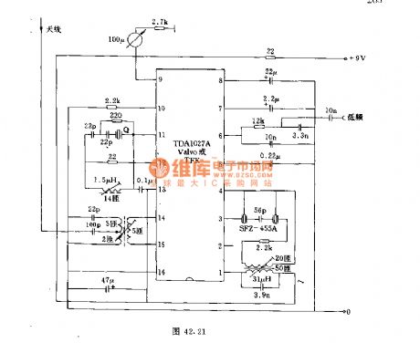
IC AM radio circuit
Published:2011/11/28 21:45:00 Author:Ecco | Keyword: IC, AM radio
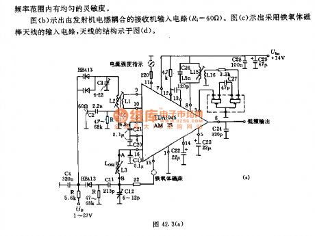
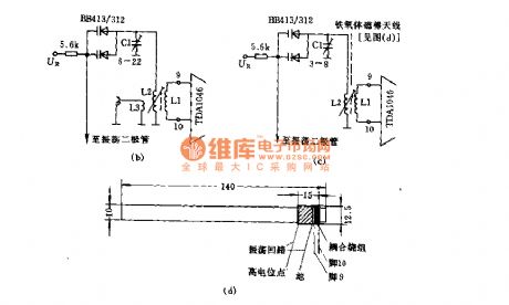
The receiver ( Figure a) input circuit is supplied by the 60Ω generator. Low -pass filter allows the entire frequency range with uniform sensitivity . Figure b shows the receiver input circuit coupled with transmitter inductive (Ri = 60Ω). Figure c shows the input circuit with ferrite ferrite antenna, the antenna structure is shown in Figure (d).
(View)
View full Circuit Diagram | Comments | Reading(3808)
FMA9901A FM dedicated antenna circuit
Published:2011/12/9 1:09:00 Author:Ecco | Keyword: FM dedicated antenna
View full Circuit Diagram | Comments | Reading(1222)
CVSD_ENCODER_FOR_SECURE_RADIO
Published:2009/7/14 4:36:00 Author:May
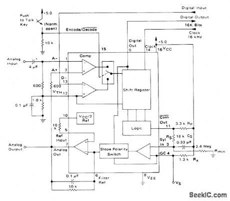
Motorola MC3417 continuously variable slope delta modulator-demodulator IC is used as 16-kHz simplex voice coder-decoder for systems requiring digital communication of analog signals. Clock rate used depends on bandwidth required and can be 9.6 kHz or less for voice-only systems. Analog output uses single-pole integration network formed with 0.1μF and 10K. Report covers circuit operation in detail for various applications.- Continuously Variable Slope Delta Modulator/Demodulator, Motorola, Phoenix, AZ, 1978. DS 9488 (View)
View full Circuit Diagram | Comments | Reading(1843)
Monolithic Stereophonic Receiver Integrated Circuit of CXA1129N
Published:2011/7/22 21:51:00 Author:Michel | Keyword: Receiver Integrated Circuit
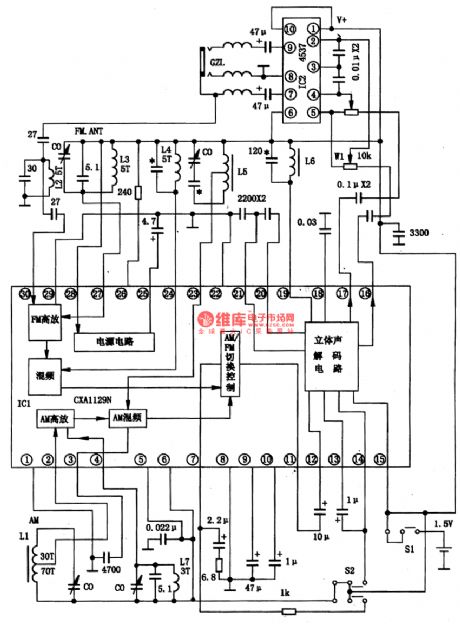
CXA1129N is monolithic stereophonic receiver integrated circuit produced by Sony.It integrates the am, FM stereo radio functions.And it saves power which can be used for one month with one A battery.
First,CXA1129N typical work voltage is 1.5V and the work current is 8mA.
Second,CXA1129N integrated block inside circuit block diagram is shown as figure 1. Figure 1 CXA1129N insdie circuit block diagram of integrated block and typical application circuit.
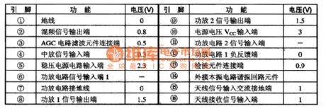
Third,Pins Functions and Data
CXA1129N uses 30 feet double row flat type plastic package with small size,the length is 10 mm and the width is 5.5 mm/ (View)
View full Circuit Diagram | Comments | Reading(3645)
Auto-radio circuit diagram
Published:2011/7/22 1:29:00 Author:Ecco | Keyword: Auto-radio
View full Circuit Diagram | Comments | Reading(1565)
TEA5551T Monolithic Radio Integrated Circuit
Published:2011/7/19 11:54:00 Author:Michel | Keyword: Monolithic, Radio Integrated Circuit
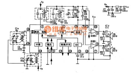
TEA5551T is monolithic radio integrated circuit prodcued by Philips of Poland.TEA5551 is widely used in small headset type radio and AM of playback.
First,Function Features
TEA5551 integrated circuit contains AM radio frequency mixing, vibration, putting, detection and AGC circuit.It has all functions such as audio power output is received by the antenna.Its inside circuit block diagram and typical application circuit is shown as picture 1-1.
Second,Pins Functions and DataPins Functions and Data of TEA5551 are shown as table 1-2.
(View)
View full Circuit Diagram | Comments | Reading(1639)
Inductance Tuning Crystal Radio Circuit
Published:2011/6/28 6:08:00 Author:Michel | Keyword: Inductance Tuning Crystal Radio Circuit

First of all,the Q value of the spherical adjustable inductance coil is measured by Q table. the capacitor The capacitor of Q table is fixed on 55pf and the measuring result is:Maximum induction:550 KHz Q = 68,Middle induction:745 KHz Q = 60,Minimum induction:2770 KHz Q = 30.The capacitor of Q table is fixed on 80 pf and the measuring result is:Maximum induction:478 KHz Q = 77,Middle induction:995 KHz Q = 47,Minimum induction:2300 KHz Q = 15.
The coil's Q value is not high,especially the inside and outside coil reverse and the Q value is lower when the inductance cancel each other out.But it can used as crystal radio receiver tuning without variable capacitor and the line is simpler. (View)
View full Circuit Diagram | Comments | Reading(1542)
Module Super-regenerative FM Radio Cirucit of Electron Tube
Published:2011/6/22 5:00:00 Author:Michel | Keyword: Electron Tube, Module Super-regenerative, FM Radio Cirucit
Devices Selection
The machine circuit is shown in the picture and it is a superregenerative receiver circuit.Because most channel frequencies work between 88MHz~108MHz and take Shanghai literature and art channel (the middle frequency is 96.8MHz)as example.L2 uses Φ2mm silver-coated copper wire.On the diameter Φ15mm mould,it can be roped into 5 circles hollow type whose coil distance is 2mm. The distances between two circles is about 2mm-3mm.The radio frequency choke uses Φ0.32mm lacquered wire.The diameter 10mm paper tube is raped into 150 circles which is divided into three sections hives and the distance is 2mm. (View)
View full Circuit Diagram | Comments | Reading(7583)
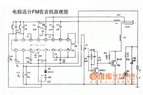
Channel Selection and FM Circuit of TDA70887 Computer
Published:2011/6/28 6:12:00 Author:Michel | Keyword: TDA70887 Computer, Channel Selection, FM, Circuit
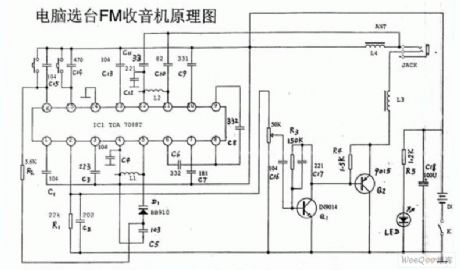
Channel Selection and FM Circuit of TDA70887 Computer (View)
View full Circuit Diagram | Comments | Reading(1780)
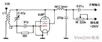
MIC Bias Circuit-1.5km Single-Tube FM Radio MIC Transmitter Circuit
Published:2011/6/10 21:34:00 Author:Robert | Keyword: MIC, Bias Circuit, 1.5km, Single-Tube, FM, Transmitter
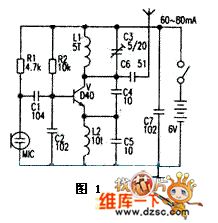
The picture 1 is a typical 1.5km single-tube FM radio MIC transmitter circuit. This circuit's key components is emission triodes which always are the D40, D50, 2N3866 and so on. Its working circuit is 60-80mA.
In amateur case it is easy to make a successful low-power radio circuit with 88~108MHz FM frequency range. This circuit has sinple single-tube transmitter circuit and also uses the integrated stereo transmitter circuit. It is mainly used for FM radio headset, wireless telephone recording forwarding, remote control, wireless alarm, monitoring, data ransmission and campus FM radio and so on.
(View)
View full Circuit Diagram | Comments | Reading(2960)
CD2003—AM/FM radio monolithic integrated circuit
Published:2011/5/10 1:14:00 Author:Fiona | Keyword: radio monolithic integrated
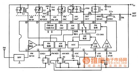
CD2003 is an AM / FM radio monolithic integrated circuit,it has been widely used in the desheng series radio.1. Features
CD2003 integrated circuit contains AM HF amplifier, local oscillator, mixer, IF amplifier and detector circuit ;FM HF amplifier, local oscillator, mixer, IF amplifier and discriminator circuit : and the AGC circuit, AM / FM band selection circuit etc, the block diagram of the in-circuit is shown in Figure 1.
Figure 1 CD2003 integrated circuit within the circuit block diagram and typical application circuit2.pin functions and data
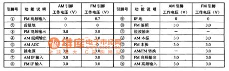
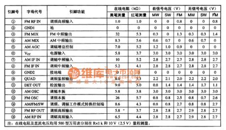
CD2003 integrated circuit uses 16-pin dual in-line Package,the pin functions and typical operating parameters(Vcc = 3V time, the pin voltage in AM and FM both cases,) are listed in table 1,the pin function and the test data on the desheng multi-band radio are listed in the table 2.
Table 1 CD2003 integrated circuit pin functions and typical operating parameters
Table 2 CD2003 integrated circuit pin functions and test data on the desheng multi-band radio
3.Typical application circuit
Illustration 1 is a typical application circuit of AM / FM band radio formed by the CD2003 integrated circuit.the work process1) AM band.The signals received from Antenna input from the CD2003 (16) pin ,mixing with the LO signal in the mixing circuit.The signal obtained output from (4) pin , obtaining the 465kHz IF signal selected by frequency to input from the (7) pin.After being converted by the IF amplification, detection, electronic switch, the signals output from (11) pin to reach the post-stage circuit. (2)FM band.The signals received from Antenna input from the (1) pin after being band-pass filtered by the BPF,added to the mixing circuit after HF amplifier.Mixing with the LO signal in the mixing circuit,the signal obtained output from (3) pin , obtaining the 10.7MHz IF signal selected by frequency to input from the (8) pin.After being converted by the AM / FM electronic switch, the signals output from (11) pin to reach the post-stage circuit.Tip:According to the above-mentioned signal flow ,it's convenient to repair AM or FM radio with sound or radio trouble.Becauce CD2003 will not easily damaged,we should pay attention to the periphery of its three-terminal filters to be checked. (View)
View full Circuit Diagram | Comments | Reading(24530)
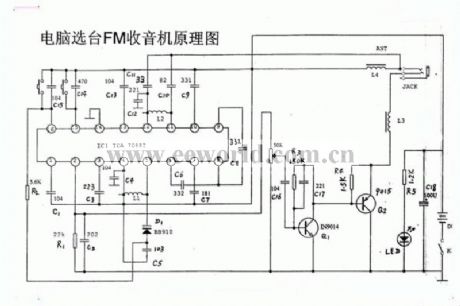
Computer automatic selecting radio circuit diagram
Published:2011/5/9 22:25:00 Author:Rebekka | Keyword: Computer automatic selecting radio
Here is the diagram of computer automatic selecting radio circuit diagram. (View)
View full Circuit Diagram | Comments | Reading(1664)
Single valve direct radio circuit diagram
Published:2011/3/30 22:14:00 Author:Ecco | Keyword: Single valve , direct radio
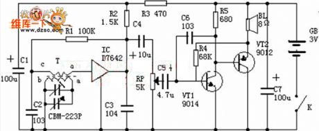
Input tuning loop: It is consisted of magnetic aerial T and 2 changeable capacitance, and its function is receiving electromagnetic wave and choosing broadcasting station. High frequency amplification and demodulation: The TA7642 is a miniature integrated circuit, the shape is similar to the triode which is shown as chart. There are 10 triodes, including third stage high amplifier, one stage demodulation and one stage. Low frequency amplification: The low frequency amplification is completed by two triode VT1, VT2 to hit the speaker of collecting electrode connecting, which converts the low frequency current as sound, the potential machine RP is used as controlling volume. (View)
View full Circuit Diagram | Comments | Reading(4214)
Car Anti-Collision Untrasonic Wave Circuit
Published:2011/4/23 3:35:00 Author:Robert | Keyword: Car, Anti-Collision, Untrasonic Wave
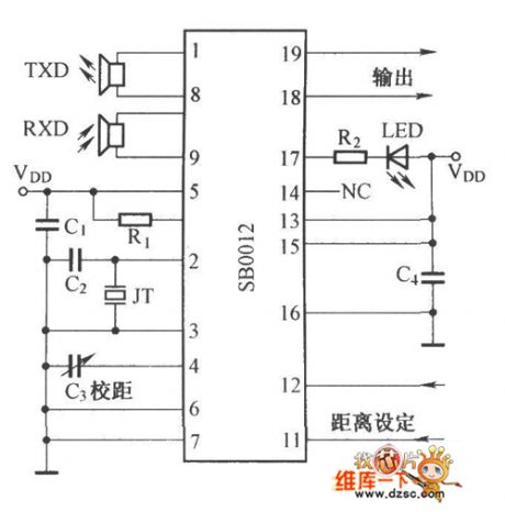
Car Anti-Collision Untrasonic Wave Circuit is shown below:
(View)
View full Circuit Diagram | Comments | Reading(1188)
| Pages:1/2 12 |
Circuit Categories
power supply circuit
Amplifier Circuit
Basic Circuit
LED and Light Circuit
Sensor Circuit
Signal Processing
Electrical Equipment Circuit
Control Circuit
Remote Control Circuit
A/D-D/A Converter Circuit
Audio Circuit
Measuring and Test Circuit
Communication Circuit
Computer-Related Circuit
555 Circuit
Automotive Circuit
Repairing Circuit