
Video Circuit
Index
Homemade MP3 player
Published:2011/8/1 3:04:00 Author:Ecco | Keyword: Homemade MP3 player
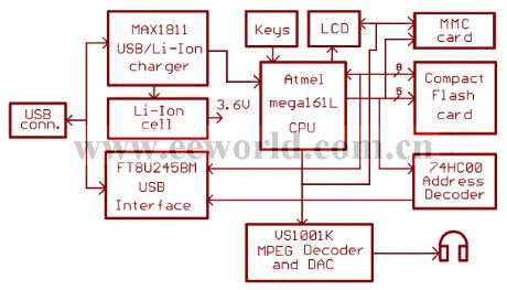
Description: This named yampp-7 MP3 player is palyed by a piece of Nokia3310 cell phone's LCD screen, and it uses a FT8U245 USB chip. A variety of flash cards and multimedia can be used the memory to store the songs.
yampp7 is a new portable MP3 player that uses Compact Flash or MultiMedia cards for storage of songs. You ll get about 1 minute of playing time per MB on the memory card, if your songs are 128 kbps. The player is pretty small and the PCB has been designed to fit into a Teko Soap box. It features a 84*48 pixel graphical LCD display, similar to the displays used on Nokia 3310 cell phones. It s designed to operate from rechargable battery cells, either from a single 3.6V Li-Ion cell (recommended), or from 3*1.2V Ni-Mh cells. With a 600 mA Li-Ion cell, the playing time is about 12 hours, but you can find Li-Ion cells up to 1200 mAh that will fit in the player, extending the playing time to about 24 hours It s intended to be used with replacement Li-Ion cells for Mobile Phones, making it easy (and relatively cheap) to find a suitable cell. (I use mine with a cell for a Motorola V3688 Phone). It also features a USB interface for fast downloading of songs to the memory card, and for firmware updates The player uses a special filesystem called YADL (Yampp Advanced Disk Layout), which maximizes the capacoty of the memory card. It is playlist based and give the player a powerful but easy to use user interface
Processor The central part of the yampp-7 player is the Atmel mega161 CPU. It s like a big-brother to the classic 8515 CPU that was used on the original yampp-3. It has 16 kB Flash and 1024 bytes internal SRAM, both double as much as on the 8515. It also features a bootloader option. This is been used in yampp-7, where it is now possible to download new firmware over the USB link USB The USB link is controlled by a FT8U245BM chip from FTDI. This is a VERY easy to use USB chip, which basically looks like a simple 8-bit buffer (hence the name).
(View)
View full Circuit Diagram | Comments | Reading(2995)
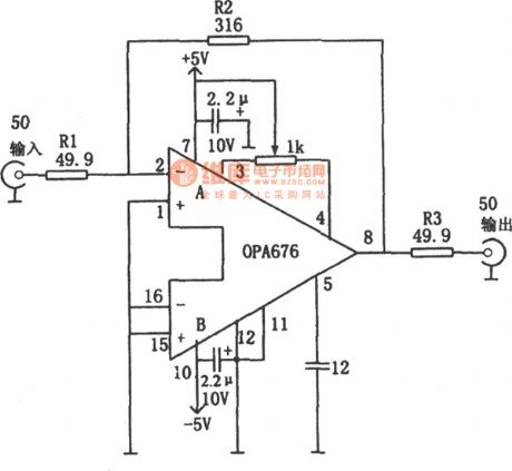
Broad Band Vedio Amplifier with 50Ω Input/Output Impedance (OPA676)
Published:2011/9/8 6:25:00 Author:Felicity | Keyword: Broad Band, Vedio Amplifier
View full Circuit Diagram | Comments | Reading(1024)
The RC phase-shift circuit with unchanged Output amplitude
Published:2011/8/7 23:42:00 Author:Sophia | Keyword: The RC phase-shift circuit, unchanged Output amplitude
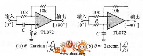
The most commonly used phase shifter phase difference is 90 °. Shown in Figure 1, in the RC phase shift circuit, even the amplitude is allowed down to 3dB, phase shift quantity is 45 °, as in the OP amplifier circuit shown in Figure 1, which is characterized by the phase shift of 0 to 180 °, 180 °to 0 , and the output amplitude does not depend on input frequency. The diagram shows the basic of RC phase circuit, the inverting amplifier of the gain A =- 1. This RC circuit can be connected to the non-inverting input terminal to decide the feedback resistance of inverting gain. If they are the same resistance value, its value can be chosen freely, actually, it is typically chosen to be 10kΩ. (View)
View full Circuit Diagram | Comments | Reading(3756)
HY8040 Typical Working Principle Circuit
Published:2011/7/18 4:54:00 Author:Felicity | Keyword: HY8040, Typical Working Principle, Circuit
View full Circuit Diagram | Comments | Reading(826)
VIDEO_PREAMP
Published:2009/6/19 5:04:00 Author:May

An NE592 or LM733 is used as a general-purpose video amplifier in this schematic. J2 and J3 provide two anti-phase outputs. R2 is a gain control. The bandwidth is about 100 MHz. (View)
View full Circuit Diagram | Comments | Reading(4)
VIDEO_SELECTOR
Published:2009/6/19 5:00:00 Author:May
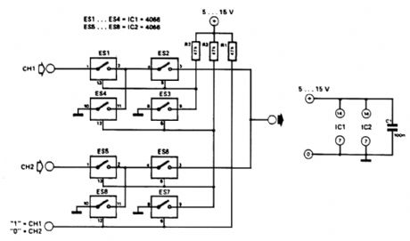
This circuit selects one of two channels with a logic signal. The unused channel is shorted out, which minimizes crosstalk. The bandwidth at -3 dB is about 8 MHz. It is advisable to buffer this cir-cuit because there is some loss in the switches when feeding a 75-Ω load. (View)
View full Circuit Diagram | Comments | Reading(4)
Crystal frequency stabilization FM circuit
Published:2011/7/16 6:05:00 Author:Fiona | Keyword: frequency stabilization, FM
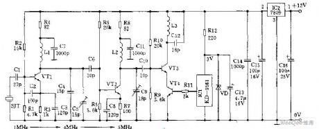
Crystal frequency stabilization FM circuit is shown as above: (View)
View full Circuit Diagram | Comments | Reading(823)
Bell of the Bicycle (the 4th)
Published:2011/6/6 5:12:00 Author:Felicity | Keyword: Bell of the Bicycle (the 4th)
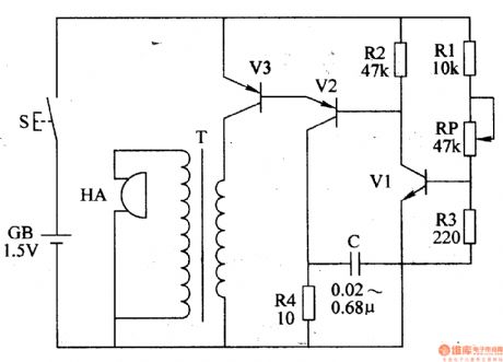
Work of the circuit
The circuit consists of LPO amplifying outputting circuit (transistor V1,V2, potentiometer RP, resistor R1-R4 and capacitor C) and power circuit (It is showed in picture 7-170.).
Press control button S and LPO begins to work. The signalwhich isproduced by LPOdrives HA to make sound “tick” after being amplified by V3.
Change the value of RP or C to change the volume. (View)
View full Circuit Diagram | Comments | Reading(693)
Bell of the Bicycle (the 3rd)
Published:2011/6/6 5:17:00 Author:Felicity | Keyword: Bell of the Bicycle (the 3rd)
Work of the circuit
The circuit consists of audio frequency oscillator, LFO and voice outputting circuit (It is showed in picture 7-169.).
When you press button S and LFO starts to work and VL shines. In the meantime audio frequency oscillator is modulated. The modulating pulse signal which is outputted from IC’s pin 3 drives BL to make the sound “honk honk”. (View)
View full Circuit Diagram | Comments | Reading(587)
Bell of the Bicycle (the 1st)
Published:2011/6/6 5:27:00 Author:Felicity | Keyword: Bell of the Bicycle (the 1st)
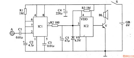
Work of the circuit
The circuit consists of monostable trigger and voice circuit. (It is showed in picture 7-167.).
When you turn on the power switch Sthemonostable trigger is in the stable condition. Loudspeaker BL makes no sound.
When our hand touches pole A the body inducted signal is supplied to IC1’s pin 2 through C1. In this situation loudspeaker BL makes sound. (View)
View full Circuit Diagram | Comments | Reading(649)
Bell of the Bicycle (the 2nd)
Published:2011/5/20 1:42:00 Author:Felicity | Keyword: Bell of the Bicycle (the 2nd)
Work of the circuit
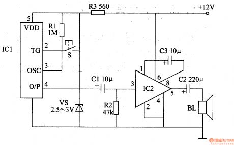
The circuit consists of voice circuit and voice-frequency amplifying circuit (It is showed in picture 7-168.).
The +12V voltage which comes from storage battery separates into two parts. One of them supplies working power to IC2 while the other one supplies 3V DC voltage to IC1.
Press button S IC1 begins to work and voice signal is outputted from its O/P. The signal drives BL make the voice “Please give way, thank you” after being amplified. (View)
View full Circuit Diagram | Comments | Reading(628)
TEA2107 Application Circuit
Published:2011/4/22 5:12:00 Author:Robert | Keyword: Application
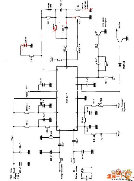
TEA2107 application circuitis shown above. (View)
View full Circuit Diagram | Comments | Reading(993)
MAX9471 Set-Top Box System Circuit
Published:2011/4/20 10:18:00 Author:Robert | Keyword: MAX9471, Set-Top Box System
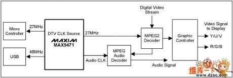
MAX9471 Set-Top Box System Circuit as shown above. (View)
View full Circuit Diagram | Comments | Reading(1290)
TEA2014 Application Circuit
Published:2011/4/20 8:17:00 Author:Robert | Keyword: TEA2014, Application Circuit
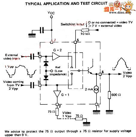
TEA2014 Application Circuit as shown above. (View)
View full Circuit Diagram | Comments | Reading(2636)
Circuit Categories
power supply circuit
Amplifier Circuit
Basic Circuit
LED and Light Circuit
Sensor Circuit
Signal Processing
Electrical Equipment Circuit
Control Circuit
Remote Control Circuit
A/D-D/A Converter Circuit
Audio Circuit
Measuring and Test Circuit
Communication Circuit
Computer-Related Circuit
555 Circuit
Automotive Circuit
Repairing Circuit