
Index 201
The linear stabilizer circuit of selectable output voltage composed of MIC5158
Published:2011/6/14 11:42:00 Author:Borg | Keyword: linear stabilizer circuit, output voltage
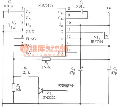
The simple constant current source circuit, in which MIC5158 is the controller, is shown in the figure. The output current of this circuit is mainly decided by the 35mV reference power supply voltage in MIC5158 and the external current limiting resistor Rs, their relation is I0=35mV/Rs. (View)
View full Circuit Diagram | Comments | Reading(823)
The self-adapted adjustable stable power supply composed of LM317
Published:2011/6/14 20:23:00 Author:Borg | Keyword: self-adapted, stable power supply
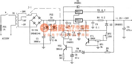
In the figure is the self-adapted adjustable stable power supply composed of LM317. This power supply has LM317 as the power supply steady element, according to the voltage value, it self-shifts the circuit input voltage, by which it reduces the difference between the input voltage and output voltage, so the power consumption of the power supply is reduced. In the circuit, VT2, VD5, VW, R5, R6, C10 and the relay K compose the self-adapted shift circuit, when the output voltage V0 is lower thant 14V, VW is blocked because of the breakdown voltage is too low, and there is no current in it, VT2 is blocked, K is still, and the connector K-1 is closed, the second-stage AC current of 14V is linked to the stable circuit. (View)
View full Circuit Diagram | Comments | Reading(1840)
The voltage stable power supply used in microprocessor drive
Published:2011/6/14 21:58:00 Author:Borg | Keyword: power supply, microprocessor drive
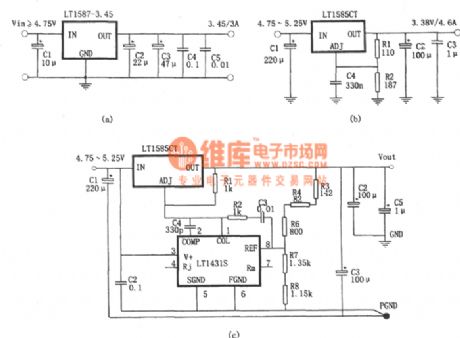
Figure (a) is the microprocessor circuit which consists of LT1587-3.45. Figure (b) is the adjustable output voltage stable power supply which consists of LT1585. Figure (C) is the microcomputer which consists of LT1584 and LT1431. The output circuits of LT1584,LT1585 and LT1587 are 7A,4.6A and 3A, which are suitable for the stabilizer which drives the microprocessor, and they characterizes high-speed passing reaction, the loading adjustment ratio is 0.5%, there are the protection circuits in them. The basic application circuit is very easy, when stabilizing the output voltage, just connect a capacitor on the input terminal and output terminal respectively. (View)
View full Circuit Diagram | Comments | Reading(835)
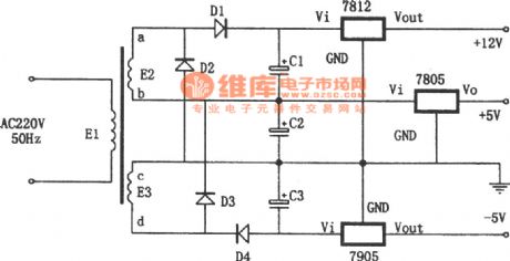
The special power supply circuit(7905,7805 and 7812)
Published:2011/6/15 0:08:00 Author:Borg | Keyword: power supply
View full Circuit Diagram | Comments | Reading(4060)
The temperature compensation positive/passive symmetric stable power supply (7812、F007C)
Published:2011/6/15 1:54:00 Author:Borg | Keyword: temperature compensation, stable power supply
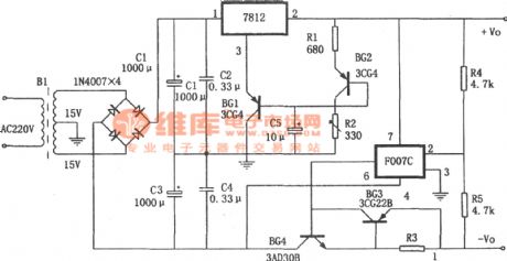
View full Circuit Diagram | Comments | Reading(1473)
The practical precise adjustable power supply
Published:2011/6/15 2:00:00 Author:Borg | Keyword: adjustable power supply
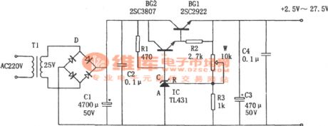
View full Circuit Diagram | Comments | Reading(1003)
Adjusting W317 stabilizer from zero
Published:2011/6/15 23:19:00 Author:Borg | Keyword: stabilizer

One of the differences between this circuit and W317 basic application circuit is that there is a team of passive voltage affiliated power supply in the circuit. The voltage on the stabilizer pipe DW positive pole to the earth is -1.25v, the lower terminal of the voltage adjusting potentiometer is not connected with the earth but with the positive pole of the pipe, the output voltage of the stable power supply is still got from the part between the output pole and earth of the 3-terminal stabilizer. So when the resistance of W is regulated to 0, the 1.25v voltage on R1 offsets the -1.25v voltage on DW, which makes the output voltage be 0v. (View)
View full Circuit Diagram | Comments | Reading(740)
The 1.25v~37v adjustable power supply composed of LM317
Published:2011/6/15 22:54:00 Author:Borg | Keyword: adjustable power supply
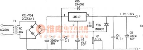
In the figure is the 1.25v~37v adjustable power supply circuit, which is a typical application cirucit of the adjustable 3-terminal stabilizer, it characterizes good functions, stable working, small size and simple installation, its maximum output current is 1.5A and its output voltage ranges from 1.25V to 37V. The circuit is suitable for experiment power supply.In the figure, C3 is used to filter to wave on RP, so that the stability of the power supply voltage is raised. Due to some reasons, when the output terminal and input terminal of LM317 are short, C2 will break the chip by releasing power in LM317, and VD6 can provide a discharging circuit for C2. (View)
View full Circuit Diagram | Comments | Reading(1198)
The +5V stable power supply with functions of current expanding and over-voltage protection(7805)
Published:2011/6/14 23:57:00 Author:Borg | Keyword: power supply, current expanding, over-voltage protection
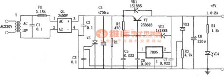
View full Circuit Diagram | Comments | Reading(1056)
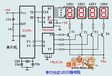
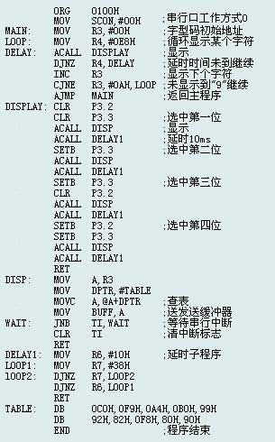
The serial port dynamic state scanning display circuit
Published:2011/6/26 22:33:00 Author:Borg | Keyword: serial port, dynamic state, display
(View)
View full Circuit Diagram | Comments | Reading(819)
The +5V and +12V circuit formed by 2 cells
Published:2011/6/27 22:23:00 Author:Borg | Keyword: +5V, +12V, cells
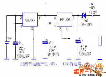
Generally, the portable electronic products powered by battery is working in a low voltage, which can reduce the number of the cells and the size of the product. Conventionally, the working voltage is 3~5V, to assure of the stability and precision, the power supply is expected to be stable. If 5V working voltage is adopted by the circuit, another higher working voltage is needed, which baffles the designer. The text is introducing a circuit composed of 2 step-up modules to solve this problem.
(View)
View full Circuit Diagram | Comments | Reading(625)
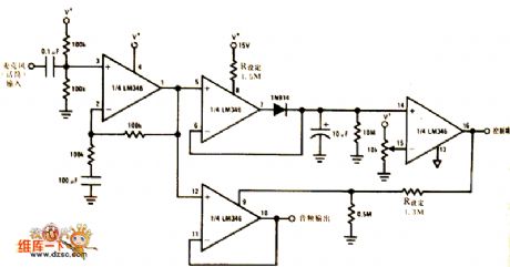
The principle diagram of the sound control switch and amplifier circuit
Published:2011/6/27 20:23:00 Author:Borg | Keyword: principle diagram, sound control switch, amplifier circuit
View full Circuit Diagram | Comments | Reading(753)
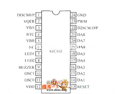
The package model and pin arrangement circuit of ATCI05
Published:2011/6/28 20:19:00 Author:qqtang | Keyword: package model, pin arrangement
View full Circuit Diagram | Comments | Reading(601)
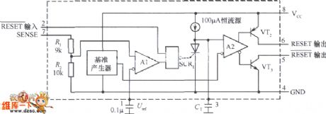
The internal circuit of voltage monitoring integrated chip TL7705CP
Published:2011/6/28 20:37:00 Author:qqtang | Keyword: internal circuit, voltage monitoring
View full Circuit Diagram | Comments | Reading(806)
The standby power supply control circuit
Published:2011/6/28 20:56:00 Author:qqtang | Keyword: standby, power supply control

View full Circuit Diagram | Comments | Reading(728)
The 110V AC-12V/8A DC switch power supply circuit
Published:2011/6/28 20:21:00 Author:qqtang | Keyword: DC, AC, switch power supply
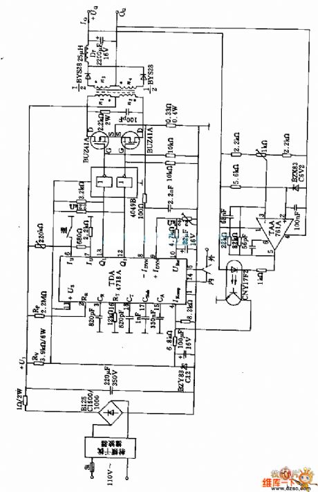
Figure:The 110V AC-12V/8A DC switch power supply circuit (View)
View full Circuit Diagram | Comments | Reading(2502)
The circuit composed of AICl783
Published:2011/6/28 20:31:00 Author:qqtang | Keyword: circuit

View full Circuit Diagram | Comments | Reading(664)
The switch power supply circuit of 220v AC-5V/10A DC
Published:2011/6/28 20:30:00 Author:qqtang | Keyword: switch power supply, AC, DC
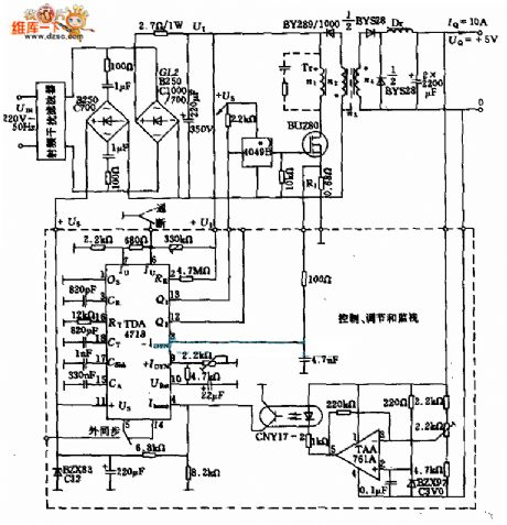
Figure:The switch power supply circuit of 220v AC-5V/10A DC (View)
View full Circuit Diagram | Comments | Reading(2229)
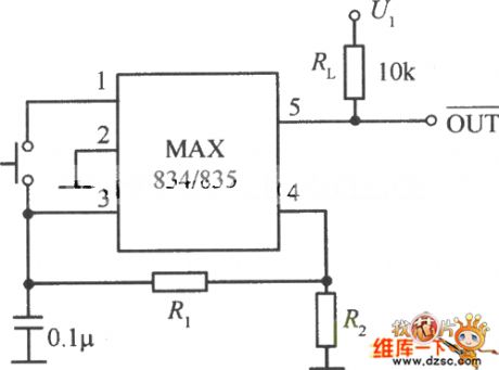
The typical application circuit of MAX834/835
Published:2011/6/28 20:35:00 Author:qqtang | Keyword: typical application
View full Circuit Diagram | Comments | Reading(722)
The 60W switch power supply circuit composed of UC3844
Published:2011/6/28 20:59:00 Author:qqtang | Keyword: switch power supply, 60W
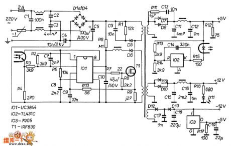
Figure:The 60W switch power supply circuit composed of UC3844 (View)
View full Circuit Diagram | Comments | Reading(3654)
| Pages:201/291 At 20201202203204205206207208209210211212213214215216217218219220Under 20 |
Circuit Categories
power supply circuit
Amplifier Circuit
Basic Circuit
LED and Light Circuit
Sensor Circuit
Signal Processing
Electrical Equipment Circuit
Control Circuit
Remote Control Circuit
A/D-D/A Converter Circuit
Audio Circuit
Measuring and Test Circuit
Communication Circuit
Computer-Related Circuit
555 Circuit
Automotive Circuit
Repairing Circuit