
Index 205
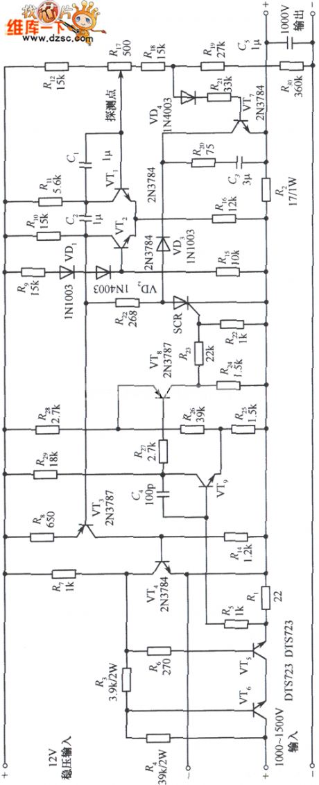
The DC regulated power supply circuit of 1000V high-voltage output
Published:2011/6/27 10:29:00 Author:Borg | Keyword: DC, regulated power supply, high-voltage
View full Circuit Diagram | Comments | Reading(1155)
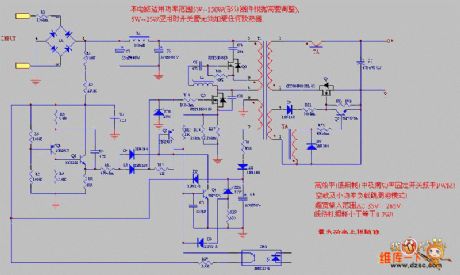
An alternative switch power supply circuit
Published:2011/6/27 10:18:00 Author:Borg | Keyword: alternative, switch, power supply
View full Circuit Diagram | Comments | Reading(1404)
The simple mixed voltage regulated circuit
Published:2011/6/27 10:00:00 Author:Borg | Keyword: mixed voltage, regulated circuit
View full Circuit Diagram | Comments | Reading(680)
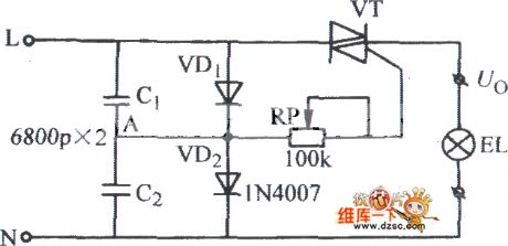
The stepless voltage regulation circuit for lights
Published:2011/6/27 10:20:00 Author:Borg | Keyword: stepless, voltage regulation
View full Circuit Diagram | Comments | Reading(688)
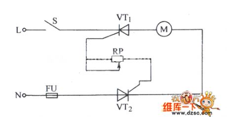
The stepless regulated circuit composed of 2 ordinary thyristors
Published:2011/6/27 10:32:00 Author:Borg | Keyword: stepless, regulated circuit, ordinary thyristors
View full Circuit Diagram | Comments | Reading(592)
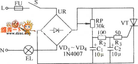
The stepless regulated circuit of thyristors
Published:2011/6/27 10:34:00 Author:Borg | Keyword: stepless, regulated circuit, thyristors
View full Circuit Diagram | Comments | Reading(703)
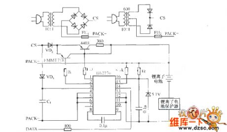
DS2770 non-regulated power supply pulse charger circuit
Published:2011/6/27 3:42:00 Author:TaoXi | Keyword: non-regulated, power supply, pulse charger circuit
View full Circuit Diagram | Comments | Reading(1197)
0.1C5A standard nickel-cadmium battery charger circuit of CD4541
Published:2011/6/20 6:09:00 Author:chopper | Keyword: 0.1C5A, standard nickel-cadmium battery, charger circuit
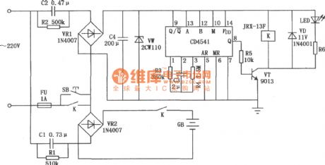
The following circuit makes use of the constant-current characteristic of capacitor and adopts pulsant direct current source to charge.Its effect is greater than pure DC,and it can charge one or more nickel-cadmium batteries.
(View)
View full Circuit Diagram | Comments | Reading(4622)
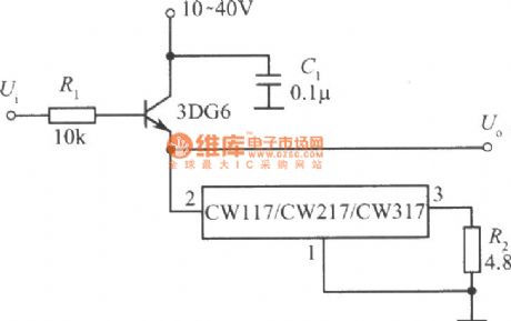
power follower of CW117/CW217/CW317 circuit
Published:2011/6/16 0:48:00 Author:chopper | Keyword: power follower
View full Circuit Diagram | Comments | Reading(1235)
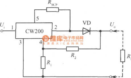
CW200 charger cirucit
Published:2011/6/16 22:07:00 Author:chopper | Keyword: charger
View full Circuit Diagram | Comments | Reading(753)
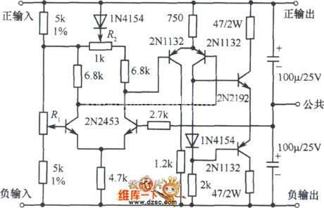
The ±5~25V dual polarity regulated power supply circuit
Published:2011/6/25 20:29:00 Author:qqtang | Keyword: dual polarity, power supply
View full Circuit Diagram | Comments | Reading(876)
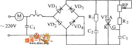
6V to 24V motorcycle battery charger circuit
Published:2011/6/20 19:23:00 Author:TaoXi | Keyword: 6V to 24V, motorcycle battery, charger
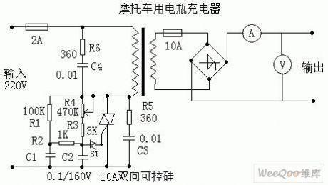
The circuit of this charger is very simple, the performance is stable and reliable, the adjustment range is wide; this circuit does not need the high-power high-current SCR and it can charge any 6V-24V batteries, the R6 and C4 make the load to approximate the resistance characteristics.
R1: 100K, R2: 1K, R3: 3K, R4: 470K (variable), R5: 360Ω, R6: 360Ω.
C1: 0.1uf / 160V, C2: 0.1uf / 160V, C3: 0.01uf / 600V, C4: 0.01uf / 600V.
ST: trigger two-way diode, two-way SCR: 10A/600V.
Transformer: about 100W, 220V/30V.
Rectifier bridge: 15A/100V.
Ammeter: 10A.
Voltmeter: 50V. (View)
View full Circuit Diagram | Comments | Reading(4531)
Battery (group) charging circuit with the adjustable charging voltage
Published:2011/6/20 20:22:00 Author:TaoXi | Keyword: Battery, group, charging circuit, adjustable charging voltage
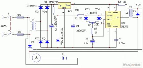
Working principle: The circuit working principle is as shown in figure 1. This circuit is composed of the power supply circuit, the trigger circuit and the main control circuit. The 220 city electricity is reduced by the power switch S-S' and the power transformer T1, and then it is rectified by the full wave rectifier circuit which is composed of the diodes VD1-VD4 to become the Pulse DC power source. One channel is limited by the resistance R1, and it is stabilized by the voltage stabilization diode DW to output the 18V trapezoidal wave synchronous manostat as the power supply of the delay link of the astable oscillator RC which is composed of the time base integrated circuit NE555 and the external components; another channel outputs the 12V stable power as the operating power supply of the trapezoidal wave synchronous power supply IC2.
(View)
View full Circuit Diagram | Comments | Reading(851)
The main circuit of the simple battery automatic constant current charging circuit
Published:2011/6/21 20:04:00 Author:TaoXi | Keyword: main circuit, simple battery, automatic, constant current, charging circuit
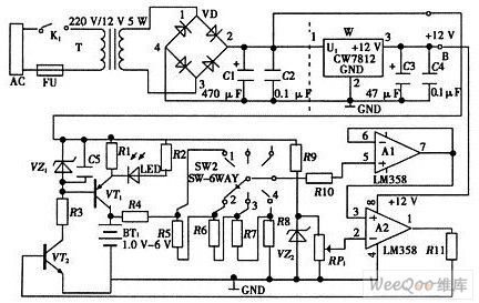
The main circuit of the simple battery automatic constant current charging circuit is as shown in the figure. It is composed of the transformer rectifier circuit, the constant current generating circuit, the charging detection circuit, the display circuit and the power supply circuit. In the main circuit, you should notice that the connection between the unit circuits must be accurately, and the overall arrangement must be reasonably.
(View)
View full Circuit Diagram | Comments | Reading(799)
Transformer rectifier circuit and the power supply circuit
Published:2011/6/21 20:19:00 Author:TaoXi | Keyword: Transformer, rectifier circuit, power supply circuit
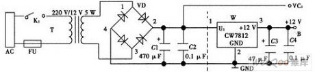
The transformer rectifier circuit and the power supply circuit is composed of the transformer, the diode bridge type circuit and the capacitance. The transformer uses the conventional iron core transformer and it changes the 220V AC electricity of the public power grid into the 12V AC electricity, and this 12V AC electricity is rectified and filtered by the diode bridge type circuit and the capacitance C1. The rectifier signal is led by VC1. If you add the three ports voltage stabilizer CW7812 and the capacitances C3 and C4 in the circuit, the whole circuit will be the voltage stabilization power supply circuit. The point B supplies the +12V DC voltage.
(View)
View full Circuit Diagram | Comments | Reading(1798)
220V AC changed into the 600V DC switch power supply circuit
Published:2011/6/21 20:30:00 Author:TaoXi | Keyword: 220V, AC, 600V, DC, switch, power supply

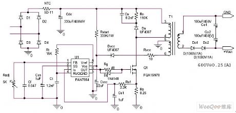
The high voltage boost power circuit: the 220V AC changed into the 600V DC switch power supply circuit.
Specifications:
Input voltage=220Vac±10%50/60Hz
Output voltage=0~600Vdc 0.25A
Switch frequency: 70~100kHz
Design guidelines:
In the DCM mode, the output power is 200W
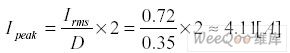
The degradation situation continuous current mode calculation formula of the input RMS current is:
If the best operating duty ratio is set to D=0.35, the calculation formula of the input peak current is:
So the voltage detection voltage level limit of the FAN7554 is 1.5V.
(View)
View full Circuit Diagram | Comments | Reading(6459)
12V DC changed into 100V AC inverter power supply circuit
Published:2011/6/21 20:41:00 Author:TaoXi | Keyword: 12V, DC, 100V, AC, inverter, power supply
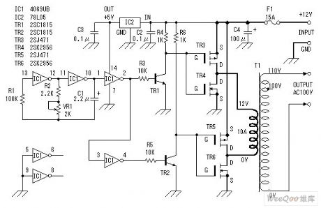
The inverter uses the power field effect transistor as the inverter device. This device uses the car battery as the supply power. So the input voltage is 12V DC. The output voltage is the 100V AC. But the input voltage and the output voltage are not limited to this. You can use any voltage. They depends on the transformer. The waveform output is the square wave. According to the experience, this circuit has the power of 100W. This circuit must be installed the fuse, because if there is too much input current, the oscillator will stop.
(View)
View full Circuit Diagram | Comments | Reading(2131)
Minitype 5V to 12V boost converter circuit
Published:2011/6/21 20:49:00 Author:TaoXi | Keyword: Minitype, boost, converter, 5V, 12V
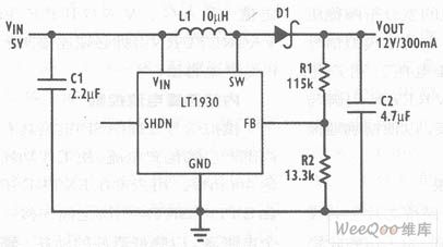
Another typical application of the LT1930 is as shown in the figure, it is the 5V to 12V boost converter. This circuit supplies the 300mA output current, the efficiency is as high as 87%. The maximum output voltage ripple wave of this circuit is 60mVp-p.
The LT1930 is the SOT-23 switching voltage regulator which has the highest power in the industry. It can be used in the boost converter, the SEPIC and the flyback converter. (View)
View full Circuit Diagram | Comments | Reading(2648)
Three 1.2V-1.5V input and 9V output booster circuits
Published:2011/6/21 21:10:00 Author:TaoXi | Keyword: 1.2V-1.5V, input, 9V, output, booster
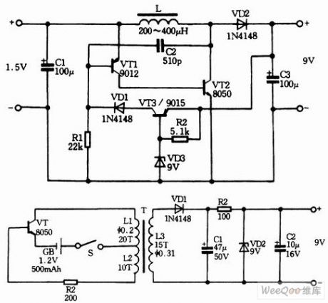
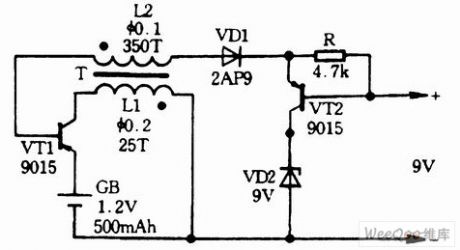
The three 1.2V-1.5V input and 9V output DC/DC circuits are as shown in the figure, it can be used in the boost battery circuit which uses the battery as the power supply.
(View)
View full Circuit Diagram | Comments | Reading(5434)
Reverse phase output four times voltage DC/DC voltage stabilization power supply circuit without inductance
Published:2011/6/21 22:02:00 Author:TaoXi | Keyword: Reverse phase, output, four times, voltage, DC/DC, voltage stabilization, power supply, inductance
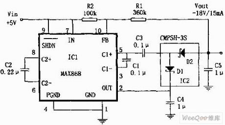
The reverse phase output four times voltage DC/DC voltage stabilization power supply circuit which is composed of the MAX868 and CMPSH-3S is as shown in the figure. The MAX868 is designed as the voltage stabilization type reverse phase charge pump integrated circuit that produces the -2VIN output voltage, the input voltage range of the VIN is 1.8~5.5V. The IC1 adjusts the output voltage through the pulse frequency modulation (PFM), the maximum frequency is 450kHz. The quiescent current is very low (30μA). We can form a reverse phase four times voltage power supply circuit by adding the charge pump which is composed of the C3, C4 and the schottky diode to the feedback loop.
(View)
View full Circuit Diagram | Comments | Reading(741)
| Pages:205/291 At 20201202203204205206207208209210211212213214215216217218219220Under 20 |
Circuit Categories
power supply circuit
Amplifier Circuit
Basic Circuit
LED and Light Circuit
Sensor Circuit
Signal Processing
Electrical Equipment Circuit
Control Circuit
Remote Control Circuit
A/D-D/A Converter Circuit
Audio Circuit
Measuring and Test Circuit
Communication Circuit
Computer-Related Circuit
555 Circuit
Automotive Circuit
Repairing Circuit