
Index 210
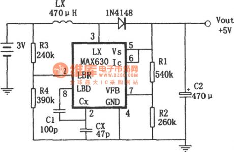
The self-bias frequency booster converting power supply composed of MAX630
Published:2011/6/14 20:41:00 Author:Borg | Keyword: frequency, booster, power supply
View full Circuit Diagram | Comments | Reading(512)
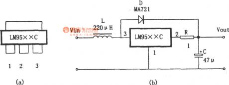
The ultra-small PWM DC/DC booster voltage stable power supply
Published:2011/6/14 4:26:00 Author:Borg | Keyword: ultra-small, DC/DC, power supply
View full Circuit Diagram | Comments | Reading(570)
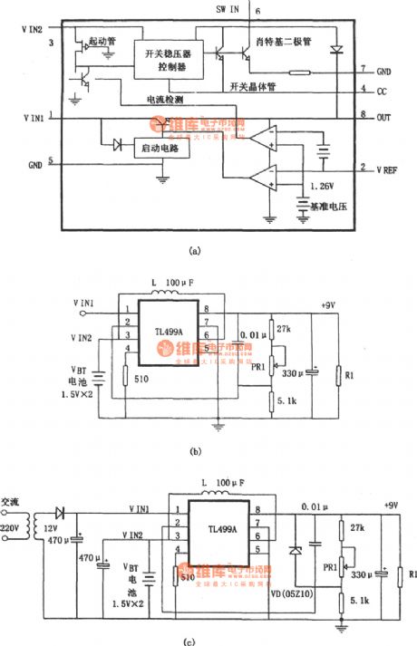
The step-up stable power supply and battery back-up power supply composed of TL499A
Published:2011/6/14 20:50:00 Author:Borg | Keyword: stable power supply, battery, back-up power supply
View full Circuit Diagram | Comments | Reading(772)
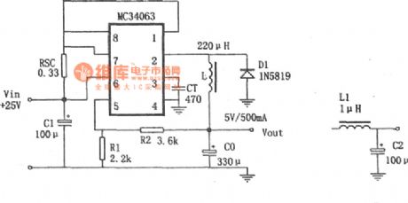
The step-down switching power supply made of MC34063
Published:2011/6/14 4:19:00 Author:Borg | Keyword: step-down, switching power supply
View full Circuit Diagram | Comments | Reading(4361)
The adjustable high-voltage regulated power supply circuit (1)
Published:2011/6/19 3:40:00 Author:Seven | Keyword: high-voltage, regulated power supply
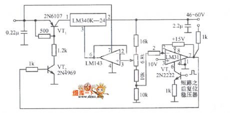
The adjustable high-voltage regulated power supply circuit (1) is shown in the figure.
(View)
View full Circuit Diagram | Comments | Reading(754)
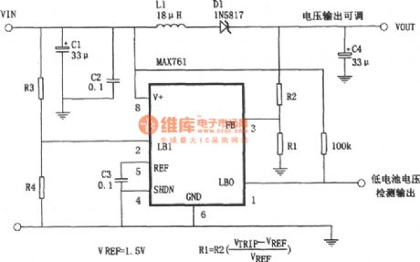
The output voltage adjustable power supply composed of MAX761
Published:2011/6/14 20:47:00 Author:Borg | Keyword: output voltage, power supply
View full Circuit Diagram | Comments | Reading(470)
The AC regulated circuit
Published:2011/6/19 8:51:00 Author:Seven | Keyword: regulated circuit
View full Circuit Diagram | Comments | Reading(493)
The DC high voltage generator
Published:2011/6/22 1:16:00 Author:Borg | Keyword: DC, high voltage
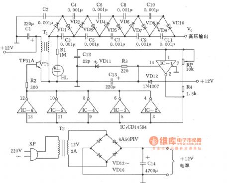
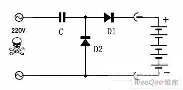
In the figure is the DC high voltage generator. It is a small-sized high voltage DC generator, which can generate the DC voltage of 10000V. (View)
View full Circuit Diagram | Comments | Reading(3409)
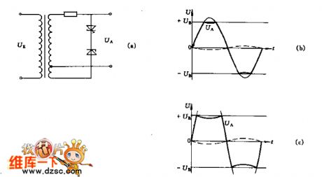
The push-pull switch power supply circuit
Published:2011/6/21 22:23:00 Author:qqtang | Keyword: push-pull, switch power supply
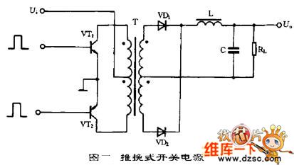
The typical circuit of the push-pull switch power supply is shown in the figure, which belongs to the 2-terminal converting circuit, the magnetic core of the high-frequency transformer is working on the two sides of the hysteresis return. The circuit is installed with two switch pipes, VT1 and VT2, the two switches are conducting and blocked in turn under the control of the external motivating square wave signals, the square wave voltage is generated at the second coil of the transformer T, and then the voltage becomes a DC voltage after it is filtered.
The virtues of the circuit is that it's easy to drive with 2 switch pipes, and the main weakness is that the withstand voltage has to be the twice of the peak value of the circuit. (View)
View full Circuit Diagram | Comments | Reading(1408)
The self-motivation switch stable power supply circuit
Published:2011/6/23 1:20:00 Author:qqtang | Keyword: self-motivation, power supply
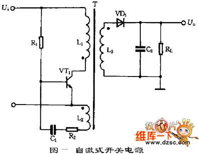
When the power supply is installed, R1 provides with starting current for the switch pipe VT1, and VT1 is conducting, whose collecting electrode current IC is linearly rising in L1, in L2, there inducts a passive forward feedback voltage that the basic pole of VT1 is positive, and the emitter is passive, which makes VT1 saturate quickly. At the same time, the inducting voltage charges C1, as the charging voltage of C1 is rising, the basic pole LEV of VT1 is getting lower, which leads to the saturation of VT1 and VT1 quits the area, IC begins to get lower, and a voltage that the basic pole is passive and the emitter is positive is inducted in L2, so VT1 is blocked quickly. (View)
View full Circuit Diagram | Comments | Reading(611)
The single terminal forward switch power supply circuit
Published:2011/6/23 1:51:00 Author:qqtang | Keyword: single terminal, forward, switch power supply
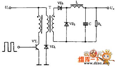
The single terminal forward switch power supply circuit is shown in the figure. This circuit is like the backward switch power supply circuit in terms, but the working condition is different. When the switch VT1 is conducting, VD2 is also conducting, at the moment, the grid is sending energy to the loading, the filter inductor L is storing energy; when the switch VT1 is blocked, the inductor L is releasing power to the loading by the freewheel diode VD3.
In the circuit, there is also a clamper coil and diode VD2, which can keep the maximum voltage of the VT1 within the twice of the power supply voltage. (View)
View full Circuit Diagram | Comments | Reading(662)
The principle circuit of the switch regulated power supply
Published:2011/6/23 1:41:00 Author:qqtang | Keyword: principle circuit, regulated power supply
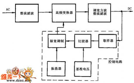
The principle circuit of the switch regulated power supply is shown in the figure.After the AC voltage is past the rectifier circuit and the filter circuit, it becomes a DC voltage which contains some impulse, the voltage flows into the high frequency converter and is turned into a wave square of needed voltage, finally, the square wave is rectified and becomes a needed DC voltage.The control circuit is a pulse width modulator, which mainly consists of sub-circuits of the sampler, the oscillator, the pulse width modulator and the reference voltage, etc. (View)
View full Circuit Diagram | Comments | Reading(512)
The basic working principle circuit of the switch regulated power supply
Published:2011/6/23 2:03:00 Author:qqtang | Keyword: working principle, regulated power supply
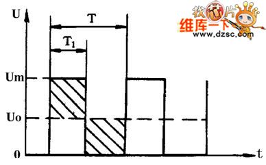
The switch regulated power supply control is classified into two types, which are the PWM type and FM type, and in the daily application, the former is used more often. In the switch power supply integrated circuits developed and used nowadays, the PWM takes the main part. Therefore, the following is mainly introducing the PWM switch regulated power supply. The basic working principle circuit of the switch regulated power supply is referred in the figure.
To a single pole rectangle pulse, the DC average voltage Uo is determined by the width of the pulse, the wider the pulse is, the higher the DC average voltage value will be. (View)
View full Circuit Diagram | Comments | Reading(619)
ICL7107--the integrated control module circuit
Published:2011/6/23 10:50:00 Author:qqtang | Keyword: integrated control, module circuit
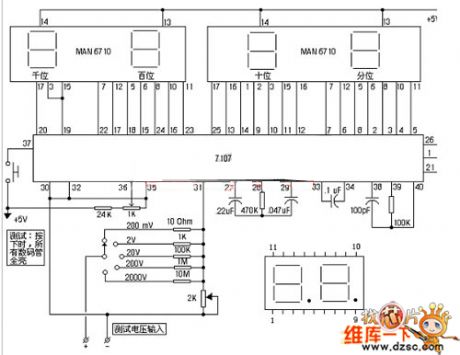
ICL7107 is a widely used integrated circuits. It contains a 3 1/2 bit digital A/D converter, which can directly drive LED digit pipes, and in it there sets the reference voltage, independent analog switch, logic control, display drive, auto reset functions and so on. Here, we introduce a type of its application circuit production--the digit voltmeter, and its circuit is in the figure. When we manufacture it, we choose the common positive digit pipes as the display, the multiple turn resistor as the 2K adjustable resistor and the metal film resistor with little difference as the divider resistor.
(View)
View full Circuit Diagram | Comments | Reading(2486)
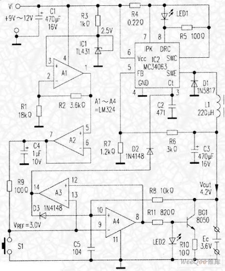
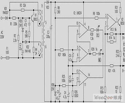
Cell phone battery charging circuit with the discharge function
Published:2011/6/22 21:50:00 Author:TaoXi | Keyword: Cell phone, battery, charging circuit, discharge function
1. Circuit and working principle:
The cell phone Lithium battery charge principle with the discharge function is as shown in the figure, the circuit structure can be divided into two parts:
(1) The discharger circuit is composed of the operational amplifiers A1-A4, the voltage regulator IC1 and the transistor BG1. The discharger core circuit is composed of the R-S flip-flop to control the conduction and on-off of the discharge tube BG1.
(2) The charging circuit is composed of the DC/DC buck type switching voltage regulator, it outputs the 4.2V voltage.
2. Component selection:
The IC1 uses the TL431, it is in the TO-92 package; the IC2 uses the MC34063, it is in the 8-pin dual-row DIP package; the A1-A4 use the LM324.
(View)
View full Circuit Diagram | Comments | Reading(1687)
1-9V regulated power supply digital display circuit
Published:2011/6/22 22:04:00 Author:TaoXi | Keyword: 1-9V, regulated, power supply, digital display
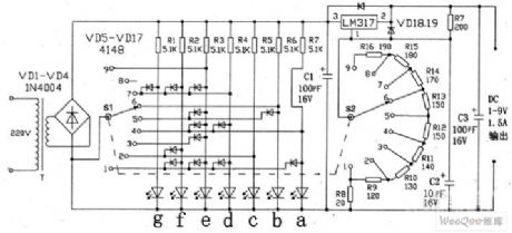
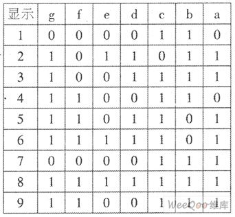
The adjustable regulated power supply which is made by the LM317 is common, the 1-9V regulated power supply additional device is as shown in the figure. This regulated power supply can output the DC 1~9V according to the need, and it chooses the red LED digital tube to display the output voltage of 1~9.
The LED digital tube 7-segment display codes are as shown in the table, the coding is finished by the S1 abd VD5~VD17 (in the table, 1 means light, 0 means extinguishing. S1 and S2 can use the band switch to restructure, the circuit is simple, with the connection method of the figure, you can do it by yourself.
(View)
View full Circuit Diagram | Comments | Reading(1340)
Simple nickel-cadmium battery charging circuit composed of three components
Published:2011/6/23 1:06:00 Author:TaoXi | Keyword: Simple, nickel-cadmium battery, charging circuit, three components
The charger of the figure is composed of three components, it is the simplest charger, this circuit is the capacitor current limiting charging circuit, the charging current is decided by the current limiting capacitance C, both the charging of one battery or more than a dozen batteries, the charge current will not change, D1 and D2 are the rectifier diodes, the current limiting capacitance need to choose the >400V non-polarity capacitor, the charge current should not exceed 100mA, if you want to charge the 500mAh number five nickel cadmium battery, the charging time is about 6 hours.
(View)
View full Circuit Diagram | Comments | Reading(2531)
6V power supply emergency light automatic charging and discharging circuit
Published:2011/6/23 1:19:00 Author:TaoXi | Keyword: 6V, power supply, emergency light, automatic, charging, discharging
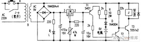
The circuit and working principle of the emergency light: the 6V power supply supplies the reference voltage for the base electrode T1, the relay J realizes the self-locking and automatic power-off of the switch K, when you connect the battery and press K, the power indicator light L turns on, and J closes, the K is locked by its contact point J-0, the charging begins, at this time the battery owes the electricity, so the emitter voltage of T1 is lower than (7.5V+0.65V), T1 and T2 cut off, they have no effect on T3. When the battery voltage is charged to 735V, the emitter voltage of T1 is 7.5V+0.65V, so T1 and T2 conduct, T3 cuts off because the base electrode voltage decreases, J releases and J-0 cuts off, the charging stops.
(View)
View full Circuit Diagram | Comments | Reading(1300)
Micro switch power supply charger circuit
Published:2011/6/23 1:22:00 Author:TaoXi | Keyword: Micro, switch, power supply, charger circuit
Micro switch power supply charger circuit (View)
View full Circuit Diagram | Comments | Reading(2188)
Nokia mobile phone travel charger circuit
Published:2011/6/23 1:29:00 Author:TaoXi | Keyword: Nokia, mobile phone, travel charger
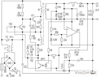
The Nokia 8210 mobile phone travel charger circuit is produced in ShangHai, the shell is labeled with: Input AC220V/50Hz(<=30mA), output 4.2V(<=200mA). In the use of charging, for the lithium battery which needs to be charged, when the voltage of the lithium battery is charged to 3.98V, the red light of the charger circuit turns off, the green light turns on. The charging time is about four hours. The author analyzes the charger and draws the circuit for reader's use and reference, the op-amp IC in this circuit is used as the comparator.
(View)
View full Circuit Diagram | Comments | Reading(1785)
| Pages:210/291 At 20201202203204205206207208209210211212213214215216217218219220Under 20 |
Circuit Categories
power supply circuit
Amplifier Circuit
Basic Circuit
LED and Light Circuit
Sensor Circuit
Signal Processing
Electrical Equipment Circuit
Control Circuit
Remote Control Circuit
A/D-D/A Converter Circuit
Audio Circuit
Measuring and Test Circuit
Communication Circuit
Computer-Related Circuit
555 Circuit
Automotive Circuit
Repairing Circuit