
Index 200
The self-made temporary 220V inverting power supply circuit
Published:2011/6/30 4:28:00 Author:Seven | Keyword: self-made, inverting, power supply
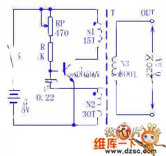
1. The principle of the circuit The transistor V, the N1 and N2 coils of transformer T and the capacitor C compose the LC oscillating circuit of transformer coupling. The potentiometer RP and resistor R provide bias current for the oscillator. 2. Element selection V is adopted with 3DD59A, R is a 1/4W general resistor, C is 0.22μF/50V, the transformer is self-made, N1 and N2 are the 0.9mm covered wire, N3 is the 0.67mm covered wire, the coil frame can be made of the 1mm hard paper board, the core would better be ferrite of U or loop shape, if not, it can be replaced by silicon-steel sheet of E or F shape.
(View)
View full Circuit Diagram | Comments | Reading(828)
MAX2003A quick charger practical circuit
Published:2011/6/30 11:11:00 Author:John | Keyword: quick charger
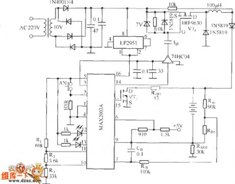
MAX2003A is the NiCad / NiMH battery’s quick charger controller circuit produced by a U.S. company. It can realize automation for the Ni-Cd / Ni-MH battery charging process and ensure the safety, flexibility and reliability of the whole charging process. MAX2003A quick charger practical circuit is shown.
(View)
View full Circuit Diagram | Comments | Reading(1666)
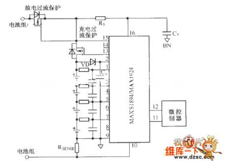
MAX1894/MAX1924 typical application circuit without pre-charging function
Published:2011/6/30 10:44:00 Author:John | Keyword: pre-charging function, typical application
View full Circuit Diagram | Comments | Reading(956)
The 3-phase SCR trigger circuit
Published:2011/6/30 4:02:00 Author:Seven | Keyword: 3-phase, SCR trigger
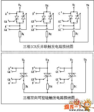
The 3-phase SCR trigger pulse order, which is launched by XMA5000 regulators, and the 6 SCR phase drifting or zero passage trigger control signals are used to control the conduction of the main control circuit. It is adopted with special trigger control circuit, which can trigger the single-way or dual-way SCR of 3A-1000A.
(View)
View full Circuit Diagram | Comments | Reading(2697)
The USB port and wall adapter charger principle circuit
Published:2011/6/30 19:22:00 Author:TaoXi | Keyword: USB port, wall adapter, charger, principle circuit
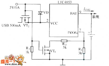
View full Circuit Diagram | Comments | Reading(792)
Typical LTC4053 USB interface Lithium ion battery charger circuit
Published:2011/6/30 19:23:00 Author:TaoXi | Keyword: Typical, USB interface, Lithium ion battery, charger circuit
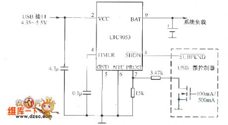
View full Circuit Diagram | Comments | Reading(770)
Notebook computer battery charging circuit composed of the BQ24700
Published:2011/6/30 19:36:00 Author:TaoXi | Keyword: Notebook computer, battery, charging circuit

View full Circuit Diagram | Comments | Reading(857)
General mobile phone battery charger circuit
Published:2011/6/30 19:50:00 Author:TaoXi | Keyword: General, mobile phone, battery, charger
View full Circuit Diagram | Comments | Reading(1305)
The classical power supply (7805 current expanding) circuit
Published:2011/6/29 4:55:00 Author:Seven | Keyword: power supply, current expanding
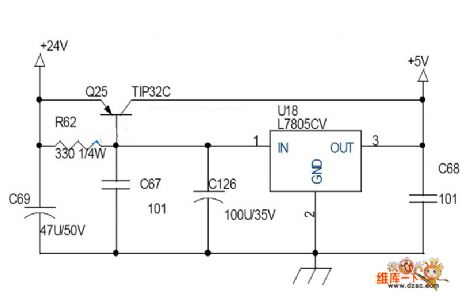
View full Circuit Diagram | Comments | Reading(1901)
The comparison of several VI converter and constant current circuits
Published:2011/6/29 4:58:00 Author:Seven | Keyword: VI converter, constant current circuits
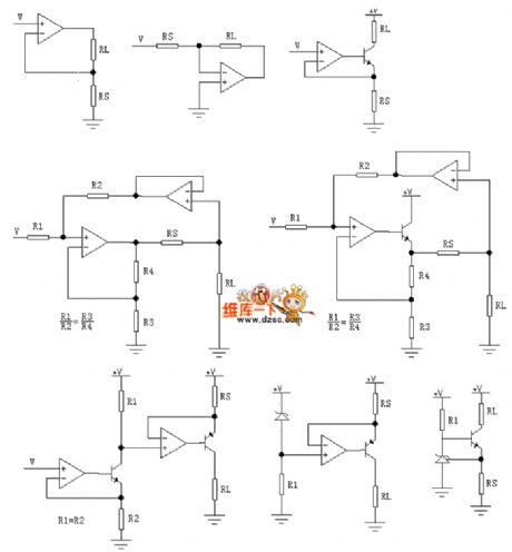
View full Circuit Diagram | Comments | Reading(1368)
The TXDl742 continuous adjusted full-automation AC regulator circuit
Published:2011/6/29 6:18:00 Author:Seven | Keyword: full-automation, AC regulator circuit
View full Circuit Diagram | Comments | Reading(661)
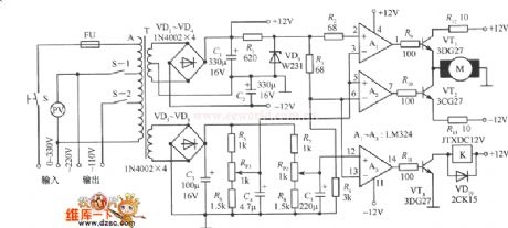
Charger for Motor Vehicle Storage Battery (the 7th)
Published:2011/6/26 9:23:00 Author:Felicity | Keyword: Charger for Motor Vehicle Storage Battery (the 7th)
Work of the circuit
The circuit consists of power circuit, pulse producing circuit and constant current charging circuit. (It is showed in picture 7-152.)
Turn on the power and the 220V AC voltage produces +15V voltage. The voltage is supplied to V and VU through R2 and R5. At the same time, GB begins charging. Change the value of RP2 and RP3 to change the charging current.
If the value of current is larger than the limited value of RP1, the pressure on V4 decreases. So the charging current is limited in a certain range.
Put S1 in the discharging position and S3 in the 50V position. Then turn off S2 and string a load between the poles of GB. At this time, GB is discharging. Put S1 in the charging position and turn on S2. Put S3 in the position of 250V. link the positive pole with the outputting positive pole. link the negative pole with the outputting negative pole. Then connect the 220V AC voltage to make it work. (View)
View full Circuit Diagram | Comments | Reading(951)
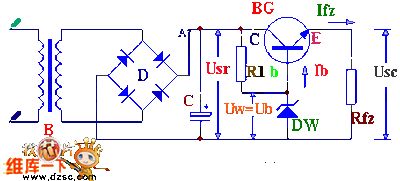
Charger for Motor Vehicle Storage Battery (the 6th)
Published:2011/6/26 9:22:00 Author:Felicity | Keyword: Charger for Motor Vehicle Storage Battery (the 6th)
Work of the circuit
The circuit consists of main charging circuit and controlling circuit. (It is showed in picture 7-151.)
Turn on the power switch S. The 220V AC is reduced by T and rectified by UR. It then produces 24V pulse DC voltage. The voltage is added to the collectors of V2 and V3. V3 outputs 20V DC voltage to work as the changing voltage of GB. Change the value of RP to change the working current of V1-V3. In that way we can change the charging current. (View)
View full Circuit Diagram | Comments | Reading(525)
Charger for Motor Vehicle Storage Battery (the 5th)
Published:2011/6/26 9:19:00 Author:Felicity | Keyword: Charger for Motor Vehicle Storage Battery (the 5th)
Work of the circuit
The circuit consists of main charging circuit and controlling circuit. (It is showed in picture 7-150.)
Turn on the battery GB and the diode VL is lightened. At this moment the pressure on GB is rather low (between 8V and 12V). The 220V AC voltage charges GB. When the voltage on GB reaches 15V, V1 is transmitted. And the charging circuit stops charging the battery. When the voltage decreases to 12.5V, the changing begins again. This keeps the voltage on GB at the value of 15V. (View)
View full Circuit Diagram | Comments | Reading(525)
Charger for Motor Vehicle Storage Battery (the 4th)
Published:2011/6/26 9:18:00 Author:Felicity | Keyword: Charger for Motor Vehicle Storage Battery (the 4th)
Work of the circuit
The circuit consists of main charging circuit and controlling circuit. (It is showed in picture 7-149.)
Turn on the power switch S1. 220V AC voltage is reduced by T1. S2 is the transforming switch of the charging output. The ammeter PA has two measuring ranges. One is 0-30A which shows the current of low-capacity battery. While the other one is 0-20A which shows the current of high-capacity battery. The controlling circuit can produce trigger pulse to control the charging current of the charger.
Change the value of RP to change the outputting current of the charger. Make sure that RP’s value is on the top before you start.
(View)
View full Circuit Diagram | Comments | Reading(847)
Charger for Motor Vehicle Storage Battery (the 2nd)
Published:2011/6/26 8:50:00 Author:Felicity | Keyword: Charger for Motor Vehicle Storage Battery (the 2nd)
Work of the circuit
The circuit consists of charging circuit and current controlling circuit. (It is showed in picture 7-147.)
Turn on the power switch S1 and the 220V voltage is adjusted. It produces pulse AC voltage. The pulse voltage is added to the positive pole of VT. Because it is not linked to GB the OSC does not work. The voltmeter PV and ammeter PA don’t work either.
When the battery is linked the OSC starts working. The voltage is added on the controlling pole of VT. The charger starts working. When the 24V battery is charged, the switch should on position a. When the 12V battery is charged, the switch should on position b.
Change the value of RP to change the current.
(View)
View full Circuit Diagram | Comments | Reading(524)
Charger for Motor Vehicle Storage Battery (the 1st)
Published:2011/6/26 8:48:00 Author:Felicity | Keyword: Charger for Motor Vehicle Storage Battery (the 1st)
Work of the circuit
The circuit consists of resistor R1, R2, stabilization diode VS and so on. (It is showed in picture 7-146.)
The AC voltage of the farm motor is rectified by UR. It then turns into AC voltage. The voltage is put on VT1 and VT2. When the pressure of GB is too low the pulse voltage is adjusted by R1 and VS. It supplies trigger voltage to VT1 to make VT1 trigged. When VT1 is transmitted the +V voltage is adjusted by R1 and VS. And VT2 is trigged too. The +V voltage charges GB through VT2. The voltage on GB is large enough and the charging stops.
(View)
View full Circuit Diagram | Comments | Reading(495)
The simple regulated circuit
Published:2011/6/29 5:03:00 Author:Seven | Keyword: regulated circuit
View full Circuit Diagram | Comments | Reading(578)
The 2.2~6V step-up circuit with the output of 7V
Published:2011/6/29 21:04:00 Author:Seven | Keyword: step-up circuit

View full Circuit Diagram | Comments | Reading(730)
The adjustable output voltage linear stabilizer circuit composed of MIC5158
Published:2011/6/14 11:24:00 Author:Borg | Keyword: adjustable output, linear stabilizer
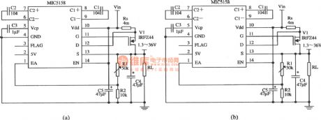
View full Circuit Diagram | Comments | Reading(590)
| Pages:200/291 At 20181182183184185186187188189190191192193194195196197198199200Under 20 |
Circuit Categories
power supply circuit
Amplifier Circuit
Basic Circuit
LED and Light Circuit
Sensor Circuit
Signal Processing
Electrical Equipment Circuit
Control Circuit
Remote Control Circuit
A/D-D/A Converter Circuit
Audio Circuit
Measuring and Test Circuit
Communication Circuit
Computer-Related Circuit
555 Circuit
Automotive Circuit
Repairing Circuit