
Index 193
FA550O switching power supply circuit
Published:2011/7/9 3:26:00 Author:chopper | Keyword: switching, power supply circuit
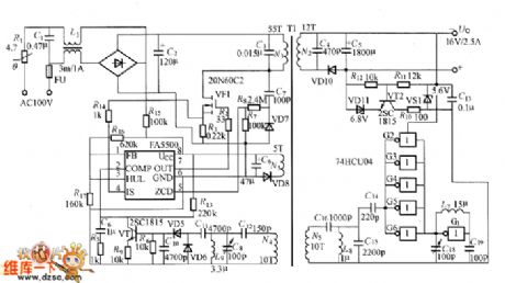
Figure shows the FA550O switching power supply,its input AC voltage is 100V, output is 16V/2.5A. FA5500 is a integrated controller, its output OUT (pin ⑦) drives grid of power M0S-FET (VF1) through the resistor R2.R3 and R14are the over-current detection resistors for VF1.VF1 undertakes switch work,making the winding N1 of transformer T1 through the pulse current.C3 is the resonant capacitor, C4 is the the capacitor in order to reduce the output impedance.Theoutput voltage of winding is converted into output DC voltage after it is commutated and smoothed by VD10 and C5.
(View)
View full Circuit Diagram | Comments | Reading(1064)
Small power switching power supply circuit with 5V/0.4A output
Published:2011/7/9 3:29:00 Author:chopper | Keyword: Small power, switching, power supply, 5V/0.4A output
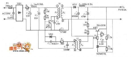
The picture shows the small power switching power supply circuit with 5V/0.4A output.The circuit adopts saturable transformer to gain the soft switch work.
(View)
View full Circuit Diagram | Comments | Reading(3550)
MA3410 practical power supply circuit
Published:2011/7/9 3:57:00 Author:chopper | Keyword: practical, power supply circuit
MA3000 series power module is power module with part resonant power supply usage,its features are that it adopts part resonant power supply design which is similar to traditional RCC design method;and it can get a constant control when the circuit is no-load;and it can be high efficiency,low noise,and miniaturization.There is over-current protection function with soft-start function and 7-shaped drooping features; it do good to the entire module package of isolation design;and the oscillation frequency range is narrow. MA3410 practical power supply is shown as picture.
(View)
View full Circuit Diagram | Comments | Reading(1010)
soft switching power supply circuit with fixed frequency
Published:2011/7/9 3:44:00 Author:chopper | Keyword: soft switching, power supply, fixed frequency
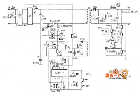
The soft switching power supply circuit with fixed frequency is shown as picture
(View)
View full Circuit Diagram | Comments | Reading(1310)
Fixed frequency common switching power supply circuit with PWM integrated controller
Published:2011/7/9 3:43:00 Author:chopper | Keyword: Fixed frequency, common, switching, power supply, PWM, integrated controller
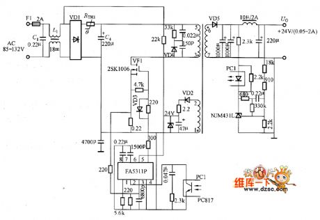
Fixed frequency common switching power supply circuit with PWM integrated controller is shown as picture
(View)
View full Circuit Diagram | Comments | Reading(1202)
part resonant converter circuit
Published:2011/7/10 3:04:00 Author:chopper | Keyword: part, resonant converter
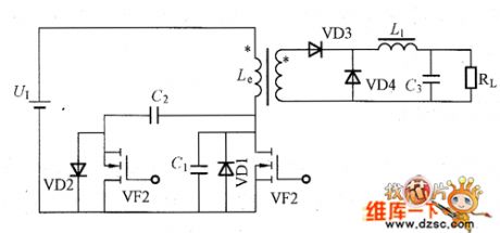
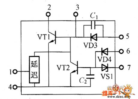
The frequency fr of resonant converter is fixed, it needs to change the switching frequency fs when the voltage regulates.As to practical current resonant converter,the conduction time of switch is constant, so fs must be reduced when the output voltage increases and the load is light.The sizes of transformers,reactors and other magnetic components are inverse proportional to the switching frequency, so we do not expect it to reduce. Now there is a part resonant converter,this converter solves the problem of high voltage of switching components in the voltage resonant converter.
(View)
View full Circuit Diagram | Comments | Reading(728)
ZCS switching power supply circuit of NE555
Published:2011/7/8 20:44:00 Author:chopper | Keyword: ZCS, switching, power supply
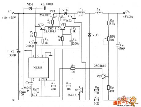
The picture shows the ZCS switching power supply circuit of NE555.This is the current resonance method(ZCS) switching power supply which is formed by adding LC series resonant circuit to step-down DC-DC converter.ZCS mode adopts fixed conduction time of resonant cycle-time to change frequency modulation.In the circuit, NE555 forms the common step-down DC-DC converter composed of voltage-controlled oscillators,switching power MOSFET (VF1),freewheeling diode YD3,smoothing inductor L2 and so on.Inductor L1, capacitor C2 constitute a resonant circuit. (View)
View full Circuit Diagram | Comments | Reading(3416)
DC power supply circuit
Published:2011/7/8 20:56:00 Author:chopper | Keyword: DC, power supply
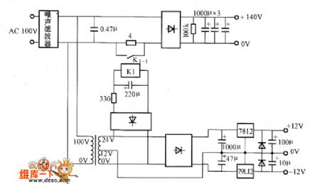
Figure shows the DC power supply circuits. AC 100V voltage is converted into a 140V DC voltage after it is commutated by the bridge rectifier and smoothed by smoothing capacity (3 1000μF capacitor in parallel), and the DC voltage is the main circuit power supply. AC 100V voltage offer stable ±12V power supply for control circuit after it is steped down by transformer,commutated by the bridge rectifier and smoothed by smoothing capacity,then regulated by 7812 and 79L12.The circuit adopts relay K1 to prevent impulse current at the moment when the power is connected.At this time,the relay K1 will stop contact K1-1, and add 4 Ω current-limiting resistor to the circuit.
(View)
View full Circuit Diagram | Comments | Reading(889)
high efficiency solar special charge management upgrating circuit-CN3083
Published:2011/7/6 7:07:00 Author:chopper | Keyword: high efficiency, solar, special charge management, upgrating circuit
Overview : CN3083 is a single lithium battery charge management chip which can be powered with solar panels.The device includes power transistor,and its application does not require the external current detection resistor and blocking diode.Internal 8-bit analog - digital conversion circuit can automatically adjust the charge current by the current output capability of input voltage supply.Users do not need to consider the worst case.It can maximize the use of the current output capability of input voltage soupply which is ideal for lithium battery charge application powered by solar panels whose current output capacity is limited. (View)
View full Circuit Diagram | Comments | Reading(1064)
low power quad voltage monitor integrated circuit--CN1185
Published:2011/7/6 6:55:00 Author:chopper | Keyword: low power, quad voltage monitor, integrated circuit
Overview : CN1185 is a low power quad voltage monitor chip,its current consumption is only 7.3 microamps,so it is ideal for monitoring battery voltage.Chip contains four voltage comparators.And the positive input end of each comparator is connected to the voltage benchmark source in the inner chip,which can be used to monitor four different voltage source or voltage source for the same grade monitoring. Users can choose the flip threshold and comparator hysteresis of the comparators by logical input port. (View)
View full Circuit Diagram | Comments | Reading(1015)
5W high-power LED driving circuit--CN5612
Published:2011/7/6 6:41:00 Author:chopper | Keyword: 5W, high-power, LED, driving circuit
overview:
CN5612 is a current modulation circuit under 2.7V-6V voltage,and constant output current is up to 1.2A.It can be used to drive various LEDs including white LEDs.The current of the LED terminal of CN5612 is through an external resistor to set the current range of 30mA to 1.2A.In the inner integrated chip there are power transistors,thus greatly it reduces the number of external components.Other functions include chip over-temperature protection, LED short / open circuit protection. CN5612 adopts 5-pinned TO252 package with good cooling capacity. (View)
View full Circuit Diagram | Comments | Reading(1378)
1W high power LED driving circuit--CN5611
Published:2011/7/8 3:03:00 Author:chopper | Keyword: 1W, high power, LED, driving circuit
Overview : CN5611 is a current modulation circuit under 2.7V to 6V,its constant output current is up to 800mA, and it can be used to drive various LEDs including white LEDs.Current on the LED end of CN5611 is through an external resistor to set the current range of 30mA to 800mA. Integrated chip contains power transistors,which greatly reduces the number of external components.Other functions include chip over-temperature protection, LED short/open circuit protection. CN5611 adopts 5 pinned SOT89 package whose cooling capacity is good. (View)
View full Circuit Diagram | Comments | Reading(1234)
high efficiency 1000MA current charger management circuit--CN3056
Published:2011/7/8 6:06:00 Author:chopper | Keyword: high efficiency, 1000MA current, charger management
Overview :CN3056 is a charger circuit which can charge rechargeable batteries like single quarter lithium ion or lithium-polymer in constant current/voltage mode.The device includes power transistor,and its application does not require the external current detective resistor and blocking diode.CN3056 only requires few external components, and works under USBbus technologyspecifications,thus it is ideal for portable applications.Heat modulation circuit can control the chip temperature within safety range if the power consumption of devices is bigger or the environmental temperature is higher.
(View)
View full Circuit Diagram | Comments | Reading(867)
Solar special USB compatible charging management circuit of high efficiency--CN3063
Published:2011/7/8 3:25:00 Author:chopper | Keyword: Solar, special, USB compatible, charging management, high efficiency
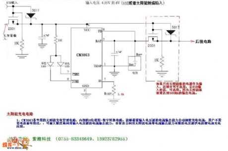
Overview :CN3063 is a single lithium battery charge management chip which can be powered with solar panels.The device includes power transistor,and its application does not require the external current detective resistor and blocking diode.The internal 8-bit analog-digital conversion circuit can automatically adjust the charge current by the current output capability of input voltage supply.Users need not consider the worst case, and it can maximize the use of the current output capability of input voltage supply.
(View)
View full Circuit Diagram | Comments | Reading(2848)
Static-free Acrylate Sheet Stocks of Shuangzhen Electronic Shenzhen/Shanghai/Dalian
Published:2011/6/24 12:30:00 Author:Michel | Keyword: Static-free, Acrylate Sheet, Stocks, Shuangzhen Electronic, Shenzhen, Shanghai, Dalian
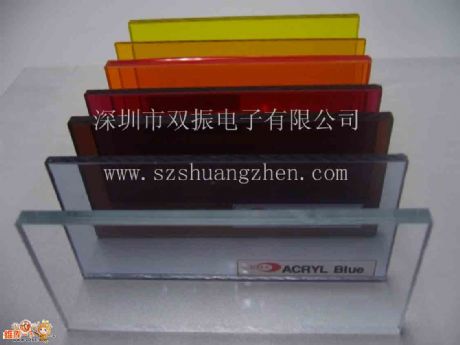
Shuangzhen Electronic Shenzhen/Shanghai/Dalian supplies static-free acrylate sheet stocks.Shenzhen Shuangzhen Electronic Co., Ltd is found in Feb. 2007 which has office and warehouses. We are specialied in providing anti-static organic glasses.We devote to providing high-quality industrial products to meet the special needs of high-tech times industry and provide good after-sales service.
Feature
The surface resistance is 10^6~1068Ω with the stable antistatic properties.
Excellent surface hardness and high chemical solvents erosion performance . (View)
View full Circuit Diagram | Comments | Reading(538)
South Korea Imported Anti-static or Shock Resistant PC Board of Shaungzhen Supply
Published:2011/6/24 12:18:00 Author:Michel | Keyword: Shaungzhen Supply, South Korea Imported, Anti-static, Shock Resistant, PC Board
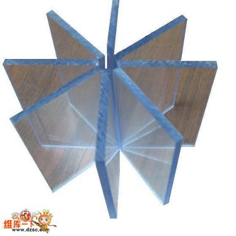
Shuangzhen supplies south Korea imported anti-static or shock resistant PC board .Shenzhen Shuangzhen Electronic Co., Ltd is found in Feb. 2007 which has office and warehouses. We are specialied in providing anti-static organic glasses.We devote to providing high-quality industrial products to meet the special needs of high-tech times industry and provide good after-sales service.
Shenzhen/Shanghai/suzhou/dalianhas anti-static PC board in stock.
Feature
The surface resistance is 10^6~10^8Ω/ with excellent antistatic properties. (View)
View full Circuit Diagram | Comments | Reading(640)
5V-12V Switch Power Supply Circuit Based on MAX761
Published:2011/6/20 22:40:00 Author:Michel | Keyword: 5V-12V, Switch Power Supply, Circuit
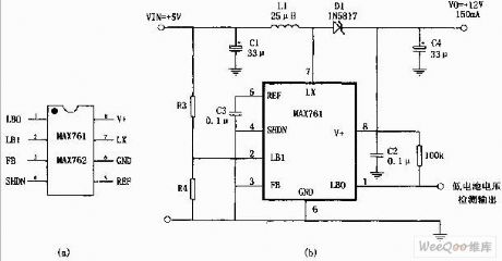
The 5V-12V boost power supply shown in the picture is composed of high efficiency,low power consumption boost DC converter,MAX761 and a few peripheral components.Its features are: First,transformation efficiency is 86%.Second,static currentis 110μA.Third, with low battery voltage detection function.R3 and R4 in the picture are testing dividing resistor and they can be caculated according to experience formula: R4=R3(VTPIP/1.5-1),VTPIP is test trigger voltage. (View)
View full Circuit Diagram | Comments | Reading(803)
Three-phase-bridge Rectifier Circuit of Resistance Load
Published:2011/6/19 7:59:00 Author:Michel | Keyword: Resistance Load, Three-phase-bridge Rectifier Circuit
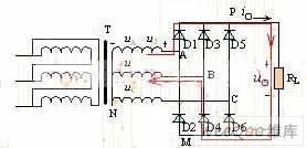
Single-phase rectifier circuit's power usually is less than one kw and high power rectifier circuit need three-phase rectifier circuit, because the high power rectifier circuit is three-phase ac power supply form. The picture is a resistance loading three-phase bridge rectifier circuit.It has six pieces of diodes,D1,D3 and D5 form cathode and are standed by P.D2,D4 and D6 form anode and M stands for them.And N stands for zero line. (View)
View full Circuit Diagram | Comments | Reading(1430)
Three LED Circuit Driven by MAX1574 Charge-Pump
Published:2011/6/19 7:24:00 Author:Michel | Keyword: Charge-Pump, Three LED Circuit
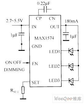
The white LED circuit driven by MAX1574 charge-pump is showed as above.This circuit uses 180mA current to drive three whiteLED.
1 MHz switching frequencies allows the charge pump touse small size ceramic capacitors.
Picture:Three LED Circuit Driven by MAX1574 Charge-Pump (View)
View full Circuit Diagram | Comments | Reading(637)
Output current expanding circuit
Published:2011/7/8 5:49:00 Author:Christina | Keyword: Output current, expanding
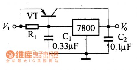
When the needed current is larger than the maximum output current of the voltage stabilizer, you can expand the output current by using the high-power transistor, the circuit is as shown in the figure.
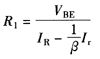
In this figure, VT is the high-power semiconductor transistor, you need to choose the semiconductor transistor according to the maximum current which needs to be expanded. The resistance value of the R1 can be decided by this formula:
In the formula:
VBE--Positive pressure drop of transistor BE, the Ge transistor is 0.3V, the Silicon transistor is 0.7V;IR--Output current of the three-port integrated voltage stabilizer;Ir--Output current of the power transistor, Ir=i. -iR.β--Amplification coefficient of the power transistor.
The circuit uses the powertransistor to expend the output current (View)
View full Circuit Diagram | Comments | Reading(665)
| Pages:193/291 At 20181182183184185186187188189190191192193194195196197198199200Under 20 |
Circuit Categories
power supply circuit
Amplifier Circuit
Basic Circuit
LED and Light Circuit
Sensor Circuit
Signal Processing
Electrical Equipment Circuit
Control Circuit
Remote Control Circuit
A/D-D/A Converter Circuit
Audio Circuit
Measuring and Test Circuit
Communication Circuit
Computer-Related Circuit
555 Circuit
Automotive Circuit
Repairing Circuit