
Index 194
LCD DC/DC Convertor Circuit
Published:2011/7/8 1:10:00 Author:Joyce | Keyword: LCD, DC/DC, Convertor
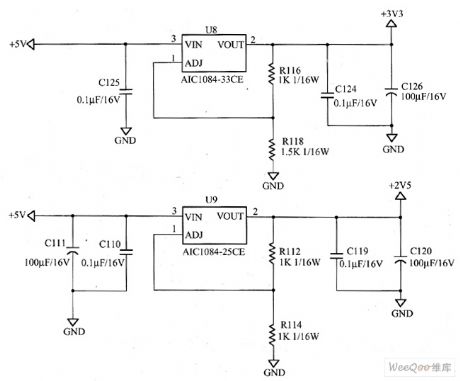
AOC LM729 LCD DC/DC convertor circuit is as shown in the following figure.
As we can see from the graph, the DC/DC converter is quite simple. Its working process is shown as follows:
A + 5 V voltage provided by switching power supply circuit will output a 3.3 V voltage through foot 2 of LDO stabilizer U8 (AIC1084-33 CE) after being stabilized by it. The output mainly supplies power for the driver board, the LCD panel and ect; A + 5 V voltage provided by switching power supply circuit will output a 2.5 V voltage through foot 2 of LDO stabilizer U9 (AIC1084-25 CE) after being stabilized by it. The output mainly supplies power for the driver board circuit. (View)
View full Circuit Diagram | Comments | Reading(968)
The Ni-Cd battery charging circuit
Published:2011/7/8 5:46:00 Author:Christina | Keyword: Ni-Cd, battery, charging circuit
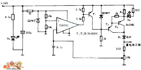
This circuit uses the automatic control and constant current charging methods, and the nominal voltage of thecharged battery is 10V, the charging termination voltage is 12V. The constant-current power supply is composed of the T2,T3 and the related components, the current value is about 4.8V/R1. Diode D1 can prevent the battery discharging when the AC power cuts off or the rectifier circuit failure. LM311 is the comparator, once the comparator is charged to the set value, it will output the low level voltage, the T1 is saturated and turns on, T2 constant-current power supply stops working, the charging process stops.
When you are charging, the LED D2 turns on; D3 can be used as the power indicator.
(View)
View full Circuit Diagram | Comments | Reading(858)
Lithium battery charging circuit with the temperature monitoring and charge status indicating functions
Published:2011/7/8 5:55:00 Author:TaoXi | Keyword: Lithium battery, charging circuit, temperature monitoring, charge status, indicating, functions
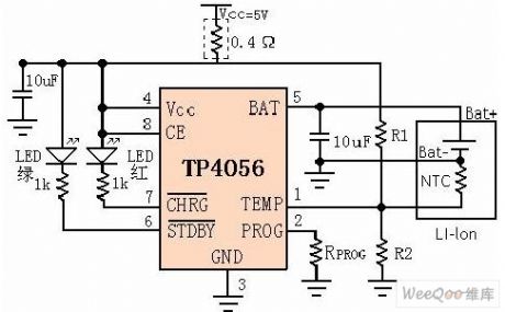
The TP4056 is designed as one kind of single lithium-ion battery which uses the constant current/constant voltage linear charger. The SOP8/MSOP8 package with the radiator in the bottom and less external components number make the TP4056 become the ideal choice of the portable applications. The TP4056 is suitable for the operating of the USB power and the adapter power. Because this device uses the internal PMOSFET architecture and the anti-reverse-charging circuit, so there is no need to use the external isolation diode. The heat feedback can automaticly adjust the charging current to limit the chip temperature in the high power operation or high environment temperature conditions.
(View)
View full Circuit Diagram | Comments | Reading(4107)
24V power supply CRT high voltage power generating circuit
Published:2011/7/8 5:54:00 Author:TaoXi | Keyword: 24V, power supply, CRT, high voltage, power generating
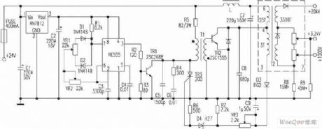
Some cameras' CRT uses the 11.4cm flat CRT as the display unit, the anode voltage of the high-voltage component is +20kv, the focusing electrode voltage is +3.2KV, the accelerating electrode voltage is +1000V, the power supply of the high-voltage component is 24V DC. The basic principle: the pulse generator is composed of the NE555, the potential regulator VR2 can make it produce the 20KHz pulse, the potentiometer VR1 adjusts the pulse width. The TR1 is the driver stage, the pulse transformer T1 uses the reverse polarity incentive. The high voltage protection circuit is composed of the D3, D9, VR3, R7 and the D4, R6, TR3. The VR2 can be used to adjust the frequency, you can adjust the high voltage by adjusting VR2.
(View)
View full Circuit Diagram | Comments | Reading(1731)
Regulator, DC-DC circuit, power supply monitor pin and main features MC33129 and other control circuits
Published:2011/7/10 10:44:00 Author:Lucas | Keyword: Regulator, DC-DC circuit, power supply monitor, pin
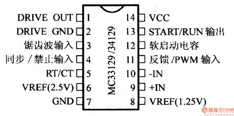
MC33129/34129 current mode switching regulator control circuit
It is the current mode switching regulator control circuit. Its output stage is the Totem form. Its supply voltage ranges from 4.2V to 12V. The maximum working frequency is 300 kHz. The maximum Zener current between the VCC terminal and START / RUN OUT side equals to 50mA. Its output current is 1.0A and ambient temperature is 70 ℃. The retention rate for mini package is 552mW. The DIP is 800mW. MC34129 works within 0 ~ +70 ℃. It contains the maximum peak switch current’s soft starting function inside, as well as low input voltage protection’s liver function. Besides, it includes over-current protection circuit with pulse lock function. (View)
View full Circuit Diagram | Comments | Reading(768)
Regulator, DC-DC circuit, power supply monitor pin and main features MC3397T and other protection circuits
Published:2011/7/10 10:44:00 Author:Lucas | Keyword: Regulator, DC-DC circuit, power supply monitor, pin
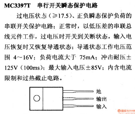
MC3397T serial switching transient protection circuit
Under the over-voltage condition (≥ 17.5), the positive and negative load protection serial switching transient protection circuit. During the normal operation, it works depending on low dropout serial component. The over-voltage leads to the off-state. When the input voltage has returned to lead state, the operating voltage under this state ranges with 4 ~ 16V. The load current is greater than 75mA and the impulse withstand voltage is ± 125V (100ms). Its maximum input voltage is ± 85V. Besides, it includes current limit and thermal cut-off circuit inside.
(View)
View full Circuit Diagram | Comments | Reading(662)
Regulator, DC-DC power supply monitor pin, main features MB3776 and other control circuit
Published:2011/7/8 0:32:00 Author:Lucas | Keyword: Regulator, power supply monitor, pin
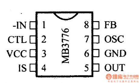
It shows the switching regulator control circuit. Its supply voltage ranges within 2.0 ~ 15V. The maximum standby current is 0.5μA and the work oscillation frequency ranges from 10 kHz to 500 kHz. And input (-IN side) voltage is limited within -0.3 ~ +10 V. Besides, the maximum collector current is 50mA. The double row DIP package is with power consumption of 550mA. Its operating temperature is between -30℃ to +75 ℃. With the dual push-pull output, it is possible to adjust internal drive circuit. And a resting time control circuit is included inside. The end of CTL can control the input and output of the power supply.
(View)
View full Circuit Diagram | Comments | Reading(793)
Regulator, DC-DC circuit, power supply monitor pin and main features MC147805 and other regulators
Published:2011/7/10 10:00:00 Author:Lucas | Keyword: Regulator, DC-DC circuit, power supply monitor, pin
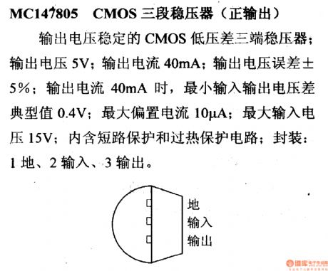
MC147805 CMOS’s three-stage regulator (positive output)
It is the CMOS low dropout three-terminal regulator with steady output voltage. Its output voltage is 5V and its output current is 40mA. The output voltage error is ± 5%. As the output current is 40mA, the minimum dropout voltage is typically 0.4V. The maximum bias current is 10μA and the maximum input voltage is 15V. It includes short protection circuit and thermal protection circuit inside. The package is with 1 ground, 2 input and 3 output.
(View)
View full Circuit Diagram | Comments | Reading(899)
Regulator, DC-DC power supply monitor pin, main features MC33065 and others control circuit
Published:2011/7/8 0:55:00 Author:Lucas | Keyword: Regulator, power supply monitor, pin
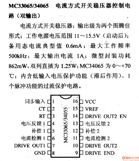
MC33065/34065 current mode switching regulator control circuit (dual output)
It is the current mode switching regulator whose output stages are formation of two totems. The regulator’s supply voltage ranges within 11 ~ 15.5V. And the standby state’s current is typically 0.6mA. The maximum working frequency is 500 kHz and the maximum output current is 1A. Besides, micro-encapsulated power consumption is 862mA. Its dual in-line is 1.25W. The MC34065 works within 0 ~ +70 ℃. Moreover, a low input voltage protection function device (hysteresis function) is placed inside, as well as a pulse overcurrent protection function circuit.
(View)
View full Circuit Diagram | Comments | Reading(665)
Regulator, DC-DC circuit, power supply monitor pin and main features MC3397T and other control circuits
Published:2011/7/10 10:42:00 Author:Lucas | Keyword: Regulator, DC-DC circuit, power supply monitor, pin
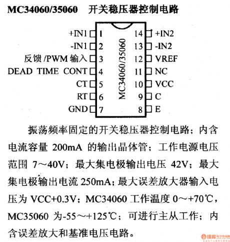
MC 34060/35060 switching regulator control circuit
It is switching regulator control circuit with the fixed oscillation frequency. It includes an output transistor with current capacity of 200mA. Its supply voltage ranges within 7 ~ 40V. The group large collector-level output voltage is 41V. And the largest collector-level output current is 250mA. The maximum input voltage of the error amplifier is VCC +0.4 V. The working temperature for 'MC34060 is from 0℃ to +70. That of the MC35060 is from- 55 ℃ to +125 ℃. It is available for master-slave working. Besides, it includes an error amplifier and reference voltage circuit.
(View)
View full Circuit Diagram | Comments | Reading(693)
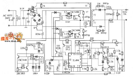
MA6540 switching power supply circuit
Published:2011/7/9 3:47:00 Author:chopper | Keyword: switching, power supply circuit
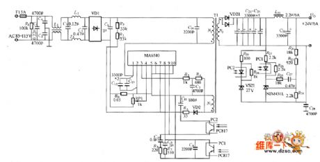
Figure shows the MA6540 switching power supply circuit,the output voltage is 24V,output current is 6A.MA6540 is the IC of excited power MOSFET with part resonance function.
(View)
View full Circuit Diagram | Comments | Reading(2731)
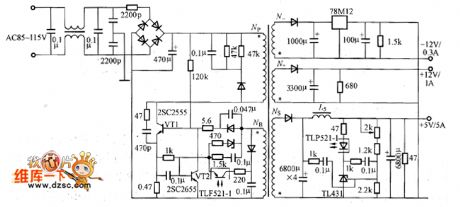
power supply circuit with 5V/15A design output
Published:2011/7/9 4:28:00 Author:chopper | Keyword: power supply circuit, 5V/15A, design output
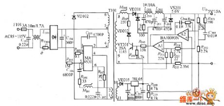
The power supply circuit whose design output is 5V/15A is as shown in picture.In the circuit, C105 is the resonant capacitor, and adopts ceramic capacitor. The chip capacitor can be used when it requires to improve the temperature characteristics.However,the current is comparative large,we should confirm the rated current of the capacitor. M101 is the delay element. C107 and R107 determine TON,and we can reduce the resistance R107 if it needs to improve the frequency.
(View)
View full Circuit Diagram | Comments | Reading(1009)
ZVS half-bridge output circuit
Published:2011/7/9 3:27:00 Author:chopper | Keyword: ZVS, half-bridge, output circuit
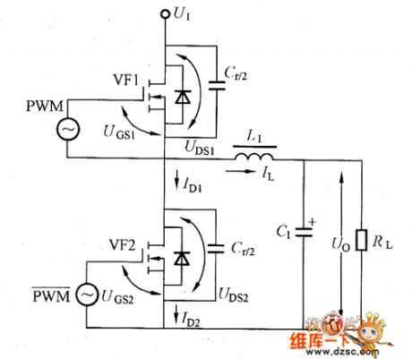
ZVS half-bridge output circuit is shown as picture
(View)
View full Circuit Diagram | Comments | Reading(2215)
low noise, efficient switching power supply circuit
Published:2011/7/9 3:40:00 Author:chopper | Keyword: low noise, efficient, switching, power supply circuit
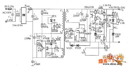
The low noise, efficient switching power supply examples composed of soft switching circuit and synchronous rectification circuit is shown as picture.Power supply output is 16.5V/3A,conversion efficiency is 88%. Although this power is designed for 16.5V voltage laptops,you can make the output voltage between 3.3 ~ 20V through changing the secondary winding turns of transformer and other component parameters like R, C.If VT1 selects 100V voltage device, the output voltage can reach 30V. The efficiency will be 82% when output is 5V,and efficiency will be 90% when output is 30V.
(View)
View full Circuit Diagram | Comments | Reading(3457)
simple RCC power supply circuit with MOSFET synchronous rectification
Published:2011/7/9 4:18:00 Author:chopper | Keyword: simple, RCC power supply, MOSFET, synchronous rectification
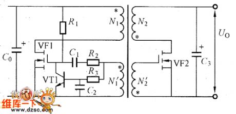
simple RCC power supply circuit with MOSFET synchronous rectification is shown as picture
(View)
View full Circuit Diagram | Comments | Reading(1688)
positive drive converter with synchronous rectification circuit
Published:2011/7/10 3:18:00 Author:chopper | Keyword: positive, drive converter, synchronous rectification
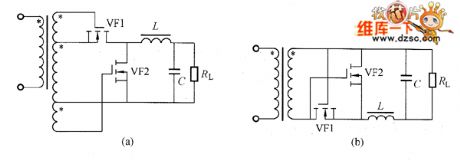
There are two current in the positive drive converter.One is the positive current through secondary winding when the primary side switching device is conductive,another is the current continued to circulate in the secondary side choke.Picture (a) is the instance of positive drive converter which adopts synchronous rectification.When the voltage of secondary winding is equal to the bias voltage of MOSFET grid,it can save some windings,just as shown in picture (b). (View)
View full Circuit Diagram | Comments | Reading(617)
typical circuit of voltage resonant converter
Published:2011/7/10 2:55:00 Author:chopper | Keyword: typical, voltage, resonant converter
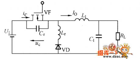
Voltage resonant circuit and current resonant circuit are in dual relationship.As to voltage resonant circuit,voltage uc(t) of switch ends is converted into sine wave voltage through resonant circuit when the switch tube is close,and the voltage is zero when switch is on/off,thus to decrease the consumption and surge.This is the so-called zero-voltage switch.
(View)
View full Circuit Diagram | Comments | Reading(595)
Half-bridge practical switching power supply circuit
Published:2011/7/10 2:39:00 Author:chopper | Keyword: Half-bridge, practical, switching, power supply circuit
Half-bridge practical switching power supply circuitis shown as picture
(View)
View full Circuit Diagram | Comments | Reading(4026)
RCC practical switching regulator circuit
Published:2011/7/10 3:06:00 Author:chopper | Keyword: RCC, practical, switching regulator circuit
RCC practical switching regulator circuit is shown as picture
(View)
View full Circuit Diagram | Comments | Reading(1592)
internal equivalent circuit of HA17385 switching power supply integrated controller
Published:2011/7/10 6:17:00 Author:chopper | Keyword: internal, equivalent, switching power supply, integrated controller
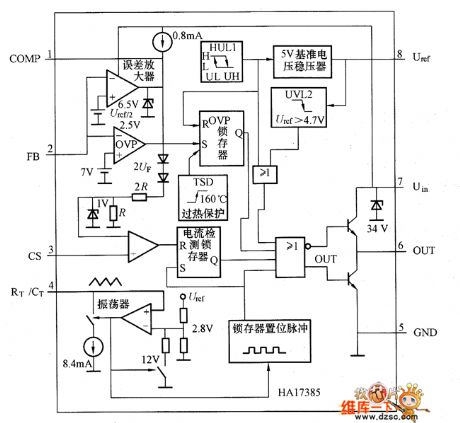
HA17385 switching power supply integrated controller uses ⑧-pin DIP package,the figure shows the internal equivalent circuit.From the equivalent circuit,we can learn that HA17385 chip includes all circuits composed of switching power supply like 5V reference voltage regulator, oscillator (triangle wave generator), the error amplifier and power MOSFET drive circuit.The maximum duty ratio of PWM wave is determined by the resistor and capacitor connected to RT/CT end of oscillator.
(View)
View full Circuit Diagram | Comments | Reading(1048)
| Pages:194/291 At 20181182183184185186187188189190191192193194195196197198199200Under 20 |
Circuit Categories
power supply circuit
Amplifier Circuit
Basic Circuit
LED and Light Circuit
Sensor Circuit
Signal Processing
Electrical Equipment Circuit
Control Circuit
Remote Control Circuit
A/D-D/A Converter Circuit
Audio Circuit
Measuring and Test Circuit
Communication Circuit
Computer-Related Circuit
555 Circuit
Automotive Circuit
Repairing Circuit