
Index 199
NE556 automatic monitoring circuit of starting battery of dynamo
Published:2011/6/20 6:22:00 Author:chopper | Keyword: automatic monitoring, starting battery, dynamo
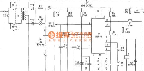
This is a automatic monitoring circuit of starting battery of dynamo,and it can detect the voltage state of storage battery continuously.When the battery discharges to the prescriptive lowest voltage,it will stop charging automatically;when the battery needs a charger but the charge power supply is not available,it can distinguish automatically and send out a acoustic signal to remind operating staff of power supply.In addition,it has a function of automatic-manually operation convertion,which makes it charge the battery at any time manually.
(View)
View full Circuit Diagram | Comments | Reading(3254)
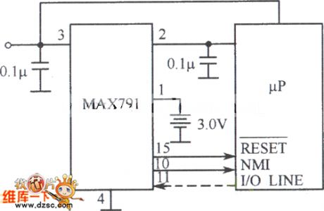
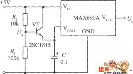
The power supply fault monitoring circuit
Published:2011/6/30 21:05:00 Author:qqtang | Keyword: power supply, fault monitoring
View full Circuit Diagram | Comments | Reading(581)
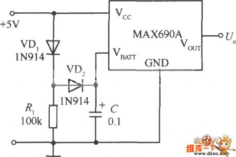
The circuit of impeding discharge of the capacitor
Published:2011/6/30 21:42:00 Author:qqtang | Keyword: discharge, capacitor
View full Circuit Diagram | Comments | Reading(596)
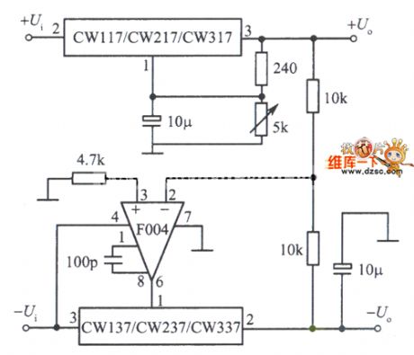
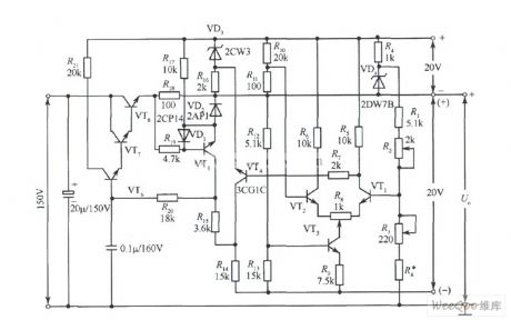
The positive and passive output voltage tracked integrated regulated power supply circuit
Published:2011/6/30 22:15:00 Author:qqtang | Keyword: output voltage, regulated power supply
View full Circuit Diagram | Comments | Reading(686)
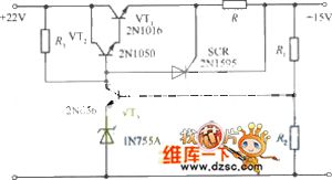
The 15V regulated power supply circuit of SCR
Published:2011/6/30 22:11:00 Author:qqtang | Keyword: regulated power supply
View full Circuit Diagram | Comments | Reading(968)
The 5V-+12V and -15V DC converter circuit
Published:2011/6/30 20:38:00 Author:qqtang | Keyword: DC converter
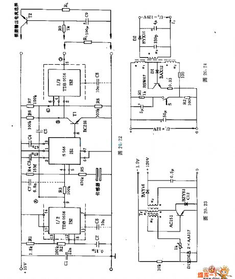
Figure: The 5V-+12V and -15V DC converter circuit (View)
View full Circuit Diagram | Comments | Reading(1799)
The auto sequence connecting power supply control ciruit
Published:2011/6/30 20:47:00 Author:qqtang | Keyword: sequence, power supply control
View full Circuit Diagram | Comments | Reading(699)
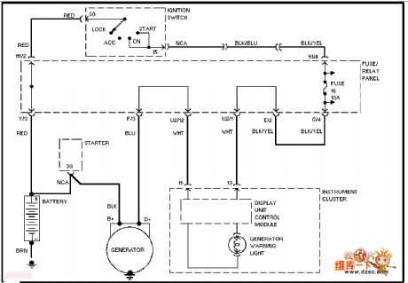
The Guangzhou Honda charging system circuit
Published:2011/6/30 20:55:00 Author:qqtang | Keyword: Guangzhou Honda, charging system
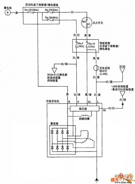
The Guangzhou Honda charging system circuit is shown in the figure.
(View)
View full Circuit Diagram | Comments | Reading(667)
The Volkswagon charging system circuit
Published:2011/6/30 20:50:00 Author:qqtang | Keyword: Volkswagon, charging system
View full Circuit Diagram | Comments | Reading(641)
The randomly set standby power supply voltage circuit
Published:2011/6/30 21:03:00 Author:qqtang | Keyword: standby power supply, voltage circuit
View full Circuit Diagram | Comments | Reading(689)
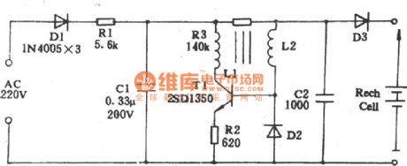
Matsushita shaver charge circuit
Published:2011/6/14 3:17:00 Author:chopper | Keyword: Matsushita, shaver, charge
View full Circuit Diagram | Comments | Reading(1595)
STR-S6709 switch power supply thick film integrated circuit
Published:2011/6/15 8:05:00 Author:chopper | Keyword: switch power supply, thick film, integrated circuit
STRS6709 is a PWN control integrated circuit of current mode,and it is applie (View)
View full Circuit Diagram | Comments | Reading(1348)
printed circuit board with enough creepage distance in the high voltage circuit
Published:2011/6/15 5:13:00 Author:chopper | Keyword: printed circuit board, creepage distance, high voltage circuit
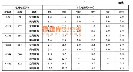
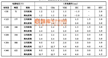
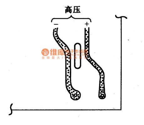
In the power supply circuit,there should be enough interval among lines for security.The interval is usually called creepage distance. A side circuit often should be added 220V voltage or above,therefore we needa creepage distance that can stand the high voltage.The usual creepage distance is 5OOV/1mm.But the distance is not enough if it is used in the high humidity environment.In this case, non-corroding resin should be printed on the surface of printed plate and so does the dampproof coating.Additionally,high voltage circuit can increase creepage distance by slotting the lines,just as follows.
(View)
View full Circuit Diagram | Comments | Reading(1367)
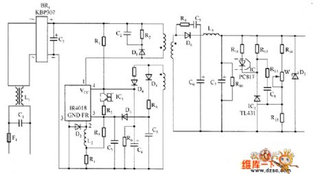
PHILIPS 170B4 LCD Monitor Switch Power Supply Circuit
Published:2011/6/30 4:31:00 Author:Joyce | Keyword: PHILIPS 170B4 , LCD Monitor , Switch , Power Supply
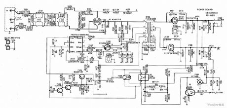
PHILIPS 170 B4 LCD monitor switching power supply takes 7101 (TEA1533) as its core component. The circuit is as shown in the figure. (View)
View full Circuit Diagram | Comments | Reading(7437)
24V Short-circuit Prevention and Regulated Power Supply Circuit
Published:2011/6/30 4:26:00 Author:Joyce | Keyword: 24V , Short-circuit, Prevention , Regulated , Power Supply
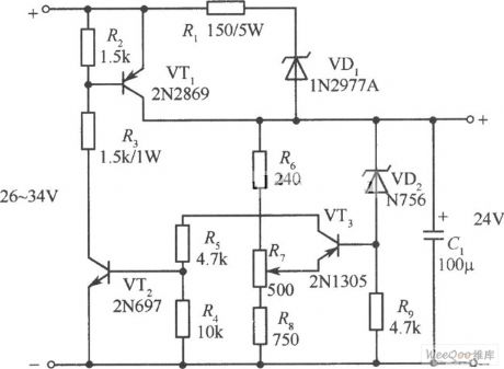
Short-circuit prevention and regulated rower supply circuit is shown as follows: (View)
View full Circuit Diagram | Comments | Reading(973)
0~30V﹑2A-based Constant Current and Regulated Power Supply Circuit
Published:2011/6/30 4:39:00 Author:Joyce | Keyword: 0~30V﹑2A-based , Constant Current , Regulated Power Supply
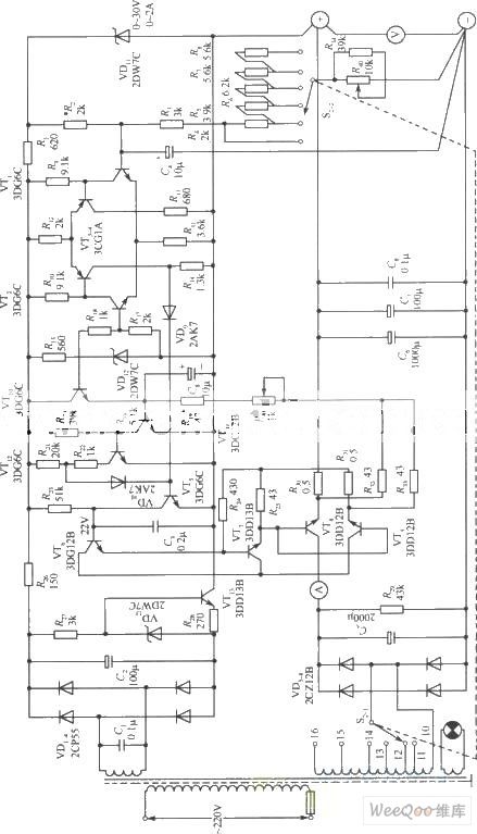
0~30V﹑2A-based constant current and regulated power supply circuit is shown in the following figure. (View)
View full Circuit Diagram | Comments | Reading(1489)
A Durable 3~120V Regulated Power Supply Circuit
Published:2011/6/30 4:41:00 Author:Joyce | Keyword: Durable , 3~120V , Regulated Power Supply
A durable 3~120V regulated power supply circuit is as shown in the figure. (View)
View full Circuit Diagram | Comments | Reading(1114)
70V Regulated Power Supply Based Circuit
Published:2011/6/30 4:45:00 Author:Joyce | Keyword: 70V , Regulated Power Supply , Based
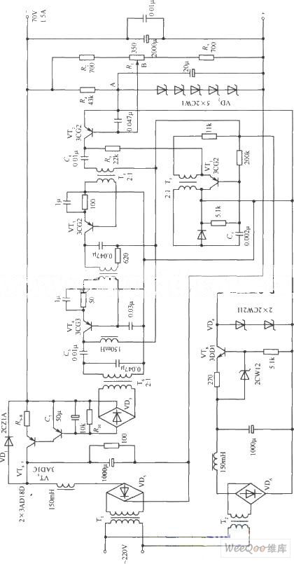
70V regulated power supply based circuit is as shown in the figure.
(View)
View full Circuit Diagram | Comments | Reading(1003)
Ordinary 1000 V High Voltage Output DC Regulated Power Supply Circuit
Published:2011/6/30 4:35:00 Author:Joyce | Keyword: Ordinary , 1000 V , High Voltage, Output , DC , Regulated Power Supply
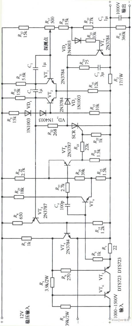
Ordinary 1000 V high voltage output DC regulated power supply circuit is as shown in the figure. (View)
View full Circuit Diagram | Comments | Reading(800)
IR4010 internal schematic box circuit
Published:2011/6/30 11:23:00 Author:John | Keyword: schematic box
The figure shows the IR4010 internal schematic box circuit, which indicates the internal circuit components of IR4010 device. It should be noted that it provides the VCC (voltage input response) with over or under voltage protection. When the VCC is equal to16 V, the control circuit starts to work with 6 V lag lock function. It refers that the circuit does not work with under-voltage protection when the VCC is less than (including) 10V. When the VCC is larger than 22V, the circuit does not work the either but with over-voltage protection.
Comparator COMP1 controls the on-and off of the MOSFET. When the VTH (1) is larger than (including).7 V, turn off the MOSFET. Comparator COMP2 controls the connection of the MOSFET. When VTH (2) is less than (including) 1.45 V, the MOSFET is connected.
(View)
View full Circuit Diagram | Comments | Reading(886)
| Pages:199/291 At 20181182183184185186187188189190191192193194195196197198199200Under 20 |
Circuit Categories
power supply circuit
Amplifier Circuit
Basic Circuit
LED and Light Circuit
Sensor Circuit
Signal Processing
Electrical Equipment Circuit
Control Circuit
Remote Control Circuit
A/D-D/A Converter Circuit
Audio Circuit
Measuring and Test Circuit
Communication Circuit
Computer-Related Circuit
555 Circuit
Automotive Circuit
Repairing Circuit