
Index 197
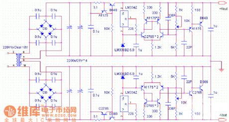
DC-Servo parallel connection voltage stabilization power supply circuit
Published:2011/7/5 19:20:00 Author:Christina | Keyword: DC-Servo, parallel connection, voltage stabilization, power supply circuit
View full Circuit Diagram | Comments | Reading(1267)
Full-automatic non-contact AC voltage stabilizer circuit
Published:2011/7/5 19:27:00 Author:Christina | Keyword: Full-automatic, non-contact, AC, voltage stabilizer
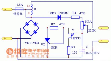
When the city electricity voltage is in the range of 150V~300V, this circuit can adjust the output voltage accurately and quickly.
The circuit is as shown in the figure. The city electricity is rectified by the VD1~VD4 and then adds to the thyristor VT, the conduction angle of VT is controlled by the BT33. The relaxation oscillator is composed of the BT33, C, R1, R2, R3 and KP, you can change the oscillation cycle by changing KP.
When the city electricity voltage increases, the voltage of BT33 increases too, the oscillation speed becomes faster, the conduction angle of VT decreases, the voltage of VT increases, so the voltage of L1 will not change. On the contrary, when the voltage of VT decreases, the voltage of L1 will not change too.
(View)
View full Circuit Diagram | Comments | Reading(8450)
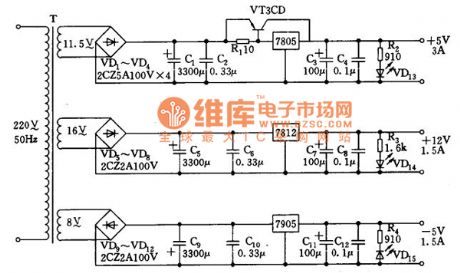
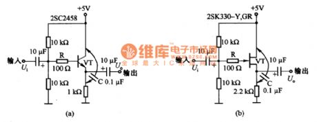
+12V, ±5V output power supply circuit
Published:2011/7/5 19:59:00 Author:Christina | Keyword: +12V, ±5V, output, power supply
View full Circuit Diagram | Comments | Reading(821)
CZX-18-type display power supply circuit
Published:2011/7/4 7:19:00 Author:John | Keyword: display, power supply
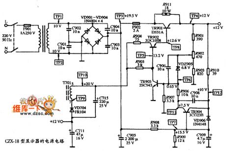
View full Circuit Diagram | Comments | Reading(674)
Monochrome display DARAS CH-5403V-type power supply circuit
Published:2011/7/4 7:17:00 Author:John | Keyword: Monochrome display, power supply
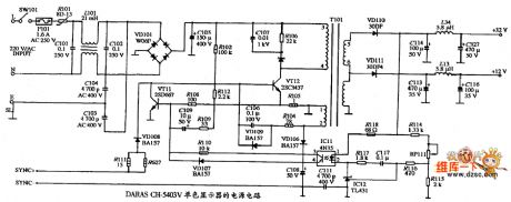
View full Circuit Diagram | Comments | Reading(668)
The 110V regulated power supply cirucit
Published:2011/6/25 5:27:00 Author:Borg | Keyword: regulated, power supply
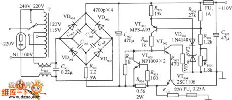
View full Circuit Diagram | Comments | Reading(691)
HT9215D-The Intergrated PC Dialing Circuit
Published:2011/6/14 23:25:00 Author:Borg | Keyword: Intergrated Circuit, PCs
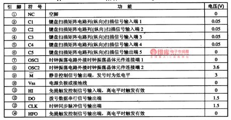
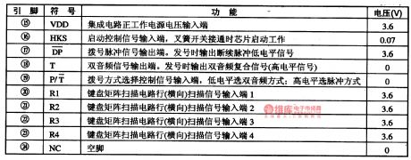
The HT9215D intergrated circuit of PC dialing is widely used in all kinds of phones.
It is pinned in dual in-line packages with 24 pinnings, whose pin functions and data are listed in Table 1-1.
le
Table 1-1 pin functions and data of HT9215D
(View)
View full Circuit Diagram | Comments | Reading(833)
The adjustable polarity inverting power supply composed of MAX764
Published:2011/6/25 5:27:00 Author:Borg | Keyword: adjustable polarity, inverting power supply
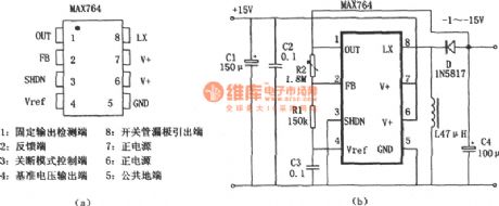
1.The stable output detect point; 8.switch pipe leakage pole exit; 2.feedback terminal; 7.positive power supply; 3.turn-off mode controller; 6.positive power supply; 4.reference voltage output terminal; 7.public ground connector. (View)
View full Circuit Diagram | Comments | Reading(773)
CW137 adjustable integrated voltage stabilizer typical application circuit
Published:2011/6/27 6:42:00 Author:Christina | Keyword: adjustable, integrated, voltage stabilizer, typical application
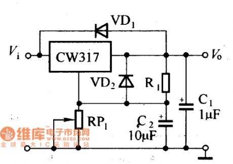
The CW137 adjustable integrated voltage stabilizer typical application circuit is as shown in the figure. The C1 is set to prevent the self-excitation of the circuit, VD1 is the protection diode. The C2 is connected between the adjust port and the grounding port of the voltage stabilizer, the function of it is to remove the ripple bypass of RP1 to improve the ripple suppression performance of the voltage stabilizer. After you add the C2 into the circuit, if the input port or output port shorts, the reverse peak current of Q will flow to the adjustment port to damage the reference voltage and the error amplifier.
CW137 adjustable integrated voltage stabilizer typical application circuit (View)
View full Circuit Diagram | Comments | Reading(738)
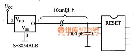
S-8054AKR application circuit diagram
Published:2011/6/30 13:33:00 Author:Sophia | Keyword: S-8054AKR, application circuit
(View)
View full Circuit Diagram | Comments | Reading(579)
The follower circuit diagram of steady operation
Published:2011/6/30 10:45:00 Author:Sophia | Keyword: The follower, steady operation
(View)
View full Circuit Diagram | Comments | Reading(558)
Pulse automatic charger 1
Published:2011/6/19 6:28:00 Author:Crystal Liu | Keyword: Pulse , automatic charger
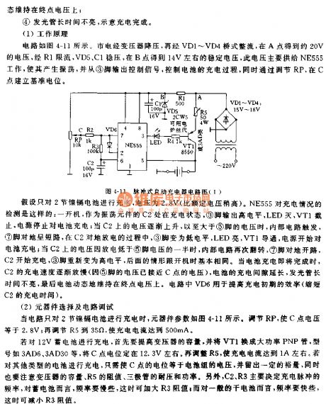
Automatic pulse charger circuit is simple, low cost, safe and fast charging.Circuit characteristics are as follows:① Pulsed current charging the battery or dry cell, to overcome the battery memory effect ;② Charging current controled by limiting resistor R5 from the adjustment, usually can be transferred to 500mA current; ③The circuit can detects the charging voltage,when the battery voltage is close to the rated voltage,charging rate gradually slowed down,maintained at the end of the battery voltage on the dynamic; ④LED does not light a long time, to indicate charge complete.
(View)
View full Circuit Diagram | Comments | Reading(694)
2CR series silicon blue-ray battery appearance circuit
Published:2011/7/4 4:14:00 Author:Christina | Keyword: 2CR series, silicon, blue-ray battery, appearance circuit
2CR series silicon blue-ray battery appearance circuit
(View)
View full Circuit Diagram | Comments | Reading(610)
2CR series silicon blu-ray battery typical application circuit
Published:2011/7/4 4:05:00 Author:Christina | Keyword: 2CR series, silicon, blu-ray battery, typical application circuit
2CR series silicon blu-ray battery typical application circuit
(View)
View full Circuit Diagram | Comments | Reading(590)
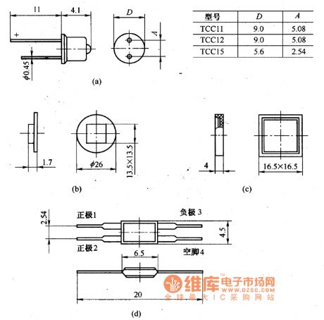
Tcc series silicon violet-blue battery circuit
Published:2011/7/4 4:03:00 Author:Christina | Keyword: Tcc series, silicon, violet-blue battery
Tcc series silicon violet-blue battery circuit
(View)
View full Circuit Diagram | Comments | Reading(581)
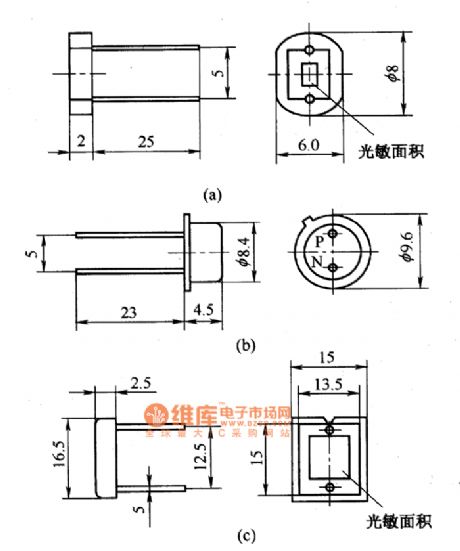
2CR series rectangular silicon photocell appearance circuit
Published:2011/7/4 6:30:00 Author:Christina | Keyword: 2CR series, rectangular, silicon photocell, appearance circuit
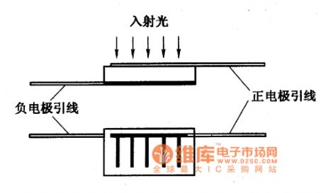
2CR series rectangular silicon photocell appearance circuit
(View)
View full Circuit Diagram | Comments | Reading(610)
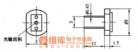
2CR series rounded silicon photocell appearance circuit
Published:2011/7/4 6:29:00 Author:Christina | Keyword: 2CR series, rounded, silicon photocell, appearance circuit
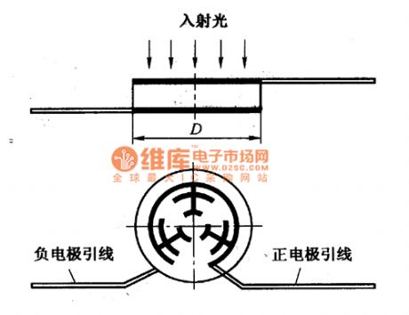
2CR series rounded silicon photocell appearance circuit
(View)
View full Circuit Diagram | Comments | Reading(555)
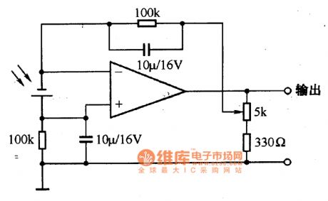
Tcc series silicon photocell appearance circuit
Published:2011/7/4 6:09:00 Author:Christina | Keyword: Tcc series, silicon photocell, appearance circuit
Tcc series silicon photocell appearance circuit
(View)
View full Circuit Diagram | Comments | Reading(734)
Precision regulated DC power supply circuit diagram made by TL431
Published:2011/7/1 2:16:00 Author:Ecco | Keyword: Precision , regulated , DC power supply
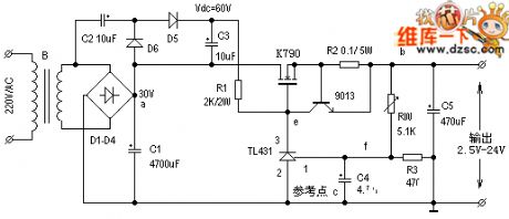
View full Circuit Diagram | Comments | Reading(6385)
Circuit Diagram of Simplified Voltage Doubler Composed of Inverter
Published:2011/7/2 22:13:00 Author:Vicky | Keyword: Simplified Voltage Doubler

The above picture is a simplest voltage doubler composed of CMOS NOT-Gate CD4069. It is probably the most basic DC/DC booster circuit. 4069, R1 and C1 together constitute a multivibrator of about 100 KHz. The output of the oscillator changes form 0 to 10V. When the output is 0V, the capacitance C2 is charged to 10V via VD1; when the output of oscillator rises to +10V suddenly, because that the two ends of capacitance cannot mutate, end A of capacitance C2 correspondently rises to +20V. Under such circumstance, VDI1 is reverse biased, and the current charges the C3 via VD2, and therefore the output end’s voltage is +20V. However, because there is pressure drop in the diode , the actual output is a litter lower than +20V. (View)
View full Circuit Diagram | Comments | Reading(1743)
| Pages:197/291 At 20181182183184185186187188189190191192193194195196197198199200Under 20 |
Circuit Categories
power supply circuit
Amplifier Circuit
Basic Circuit
LED and Light Circuit
Sensor Circuit
Signal Processing
Electrical Equipment Circuit
Control Circuit
Remote Control Circuit
A/D-D/A Converter Circuit
Audio Circuit
Measuring and Test Circuit
Communication Circuit
Computer-Related Circuit
555 Circuit
Automotive Circuit
Repairing Circuit