
Index 188
A simple without transformer converter circuit
Published:2011/7/16 7:24:00 Author:Fiona | Keyword: without transformer, converter
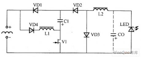
A simple without transformer converter circuit is shown as above.Input rise and fallvoltage level circuit is composed of VD4,L1,C1,VD1 in series,the output reduction voltage level is composed of the L2,VD3,VD2,CO.The two levels of conversion level common using power is decided by MOSFI tube's V1.Input rise and fallvoltage level circuit works in Intermittent mode(DCM); when the output level works,the working is in continuous mode (CCM).
(View)
View full Circuit Diagram | Comments | Reading(719)
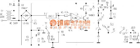
The simple automatic charger
Published:2011/7/17 19:26:00 Author:TaoXi | Keyword: simple, automatic, charger

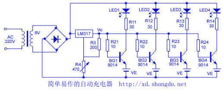
This circuit is simple, the components are easy to find, it charges the nickel cadmium batteries respectively, when the power is full, the circuit will stop automaticly. The circuit is as shown in the figure, before the charging, you need to adjust R4 to make the output voltage of the three-port adjustable voltage stabilizer is Vo, when the voltage Ve of the charging battery rises to Vo-0.65V, the transistor will cut off and the charging is terminated, at the same time, the corresponding charge indicator light LED turns off. The charging current is limited by R11-R14.
(View)
View full Circuit Diagram | Comments | Reading(884)
Simple charger circuit 7812
Published:2011/7/17 19:37:00 Author:TaoXi | Keyword: Simple, charger
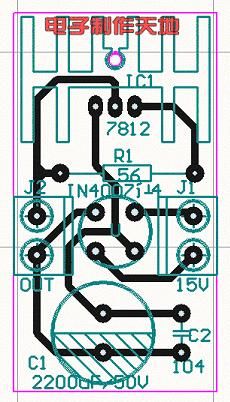
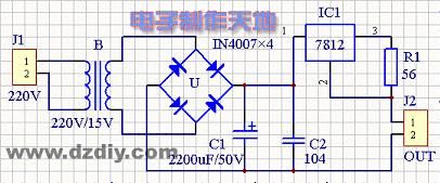
General batteries all use the constant current charging mode, so you only need to control the charging time to finish the charging. This battery looks like the NI-MH battery(nickel-metal hydride battery), the capacity is 1450 mA. The standard charging method: you need to charge the battery with the 1/10 current for 14-16 hours. This charger's charging current is 170mA, the charging time is about 12 hours. It is composed of a transformer, a 7812 three-port voltage stabilization IC, four IN4008 diodes, a 2200UF/50V electrolytic capacitor, a 0.1uF non-polarity capacitor, a 56 ohms resistor, a battery box, a circuit board and some wires.
(View)
View full Circuit Diagram | Comments | Reading(3879)
Principle and maintenance circuit of the home charger
Published:2011/7/17 20:25:00 Author:TaoXi | Keyword: Principle, maintenance, home charger

Operating principle:
The charger is a transformer step-down and diode rectification circuit. The charging process of the storage battery is the conversion process between the electric energy and chemical energy, The key technology of the charger is to slove the conversion efficiency of the electric energy and chemical energy.
From the perspective of energy conversion, the charging process of the storage battery has two kinds of modes: the constant voltage charging and constant current charging. The constant current charging can be used in the situation of large current and concentrated charging. Most of the Nickel-cadmium storage batteries use the constant voltage charging mode.
(View)
View full Circuit Diagram | Comments | Reading(659)
High efficiency current adjustable lead-acid battery charger circuit
Published:2011/7/17 21:01:00 Author:TaoXi | Keyword: High efficiency, current, adjustable, lead-acid battery, charger
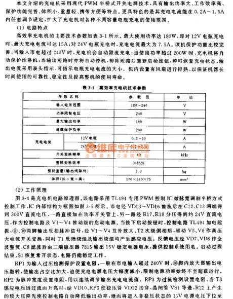
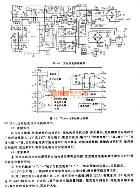
The main technical parameters of the high efficiency charger is as shown in table 3-1. The maximum power is 180W, when it charges the 12V storage battery, the maximum charging current is 15A; when it charges the 24V storage battery, the maximum charging current is 7.5A. This device has the perfect protection function, when the input city electricity is more than 240V, the charger will change into the current-limit chagring state automaticly; when the power is more than 200W, the charger will change into the protective stop state automaticly; when the output is short circuit, it will change into the protective stop state too, and after you excluding the short-circuit and restart the button, it will recover the charging state.
(View)
View full Circuit Diagram | Comments | Reading(1798)
Dry cell charger circuit (2)
Published:2011/7/17 21:43:00 Author:TaoXi | Keyword: Dry cell, charger
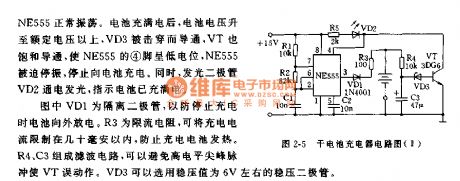
You can make a strong-function high efficient dry cell charger by using the NE555 time base integrated circuit as the core, and add some external components.
The dry cell charger circuit is as shown in figure 2-5. The low-frequency multivibrator is composed of the NE555 and the external components R1,R2,C1, when the voltage of pin-3 is the high level, you can charge the four dry cells through VD1 and R3. The oscillation frequency of the oscillator is decided by R1, R2, C1, according to the data of the figure, the oscillation frequency is about 80Hz, the electrical level of pin-3 changes with this 80Hz frequency.
(View)
View full Circuit Diagram | Comments | Reading(1341)
Multi-functional charger circuit (2)
Published:2011/7/17 22:11:00 Author:TaoXi | Keyword: Multi-functional, charger
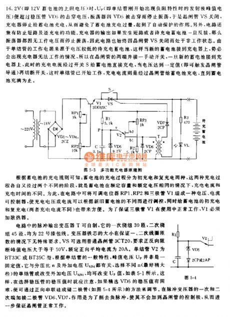
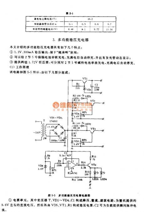
You can make the pulse output transformer T by yourself, the primary winding of it is 30 turns, the secondary winding of it is 45 turns, they are the No. 22 enameled wire. The transformer core has no special requirements, it ensures the turns of the primary and secondary coils. The VS can use the ordinary thyristor 3CT20, the positive and negative blocking peak voltage is more than or equal to 50V, the rated average forward current is 20A. The single-junction tube V2 is the BT33C or BT35C. According to the general characteristics of single-junction tube, the peak voltage Vp is not the fixed value, it has relationship with the voltage divider ratio n and the external voltage Ub2b1. You can change the value of Up by selecting the different single-junction tubes or changing the external voltage.
(View)
View full Circuit Diagram | Comments | Reading(1002)
Dry cell charger circuit (1)
Published:2011/7/17 21:14:00 Author:TaoXi | Keyword: Dry cell, charger
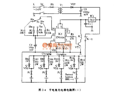
The dry cell charger circuit is as shown in figure 2-4. This circuit uses a timer chip and a relay. You can choose the timing time by adjusting the rotary switch S3, the timing range is 3-9 hours. IC2 timer integrated circuit is the universal device that can produce the long-term accurate timing. For the AA-size batteries, the optimum charging time is 5 hours, but the C-size dry cell is 9 hours.
The timer is started by the button S1, the charging LED turns on randomly, the transistor VT1 makes the relay K act, so the charging begins. When the selected charging time is up, the relay releases, and the LED which means that the charging is complete will turn off.
(View)
View full Circuit Diagram | Comments | Reading(1632)
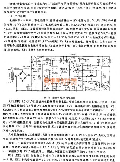
Automatic charging and discharging circuit
Published:2011/7/14 19:29:00 Author:TaoXi | Keyword: Automatic, charging, discharging
Operating principle
The circuit is as shown in the figure 4-4. The city electricity is reduced, rectified and filted by the circuit to output the +18V power supply voltage, the voltage stabilization circuit is composed of V1, R1, VD5, this voltage stabilization circuit outputs the +12V voltage to the whole circuit through the emitter V1. The +9V voltage stabilization circuit is composed of R2, C2, VD6, it supplies the power to the NE555. The 1Hz pulse signal generator is composed of the NE555 and the external components, it outputs the time pulse signal from pin-3, the waveform is as shown in the figure. The time pulse signal gets into the reversed phase amplifier V2 through the normally closed contact point K2-2 to drive the cut-off and conduction of V3, V4 directly. When the V3 is conducting and the V4 is cutting off, the +12V voltage charges the battery through VD8, V3, R7.
(View)
View full Circuit Diagram | Comments | Reading(771)
Common battery charger circuit
Published:2011/7/14 20:23:00 Author:TaoXi | Keyword: Common battery, charger
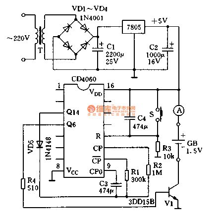
The DC 5V power supply is added to the positive electrode port of the battery GB through the ammeter to produce the 500mA interval-type charging current. After charging about one hour and a half, the high level which is output by pin-3 of CD4060 makes the oscillator stop working through the diode VD5, at this time, the Q6 outputs the low level, the power tube V1 cuts off, the charging stops. If you want to charge the other batteries, you just need to reopen the power or press the reset button S.
The charging case of one battery is as shown in figure 2-1. If you need to charge 4 series No.1, 2 or 5, 7 batteries, you need to improve the charging voltage to 9V or 15V.
(View)
View full Circuit Diagram | Comments | Reading(1100)
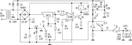
Nickel cadmium battery automatic charger and discharger circuit
Published:2011/7/14 20:34:00 Author:TaoXi | Keyword: Nickel cadmium battery, automatic, charger, discharger
Charging process: if you set the switch S to position 1 , and put the batteries into the battery clip, then connect the power, the pin-2 of TL082 has the voltage of 3V, but the pin-3 voltage is lower than 3V, the pin-1 outputs the negative voltage, BG cuts off, J has no current, the normally closed contact point J1 closes, the power charges the battery through the R8, S2, J1. When the battery voltage is higher than 3V, the output voltage of pin-1 is positive to conduct the BG, J gets power to cut off J1, the charging completes. At this time the pin-3 of TL082 has the higher voltage which is supplied by R8 and S2 to maintain J's conduction until the power is cut off.
(View)
View full Circuit Diagram | Comments | Reading(751)
Nickel cadmium battery automatic charging and discharging device
Published:2011/7/14 20:37:00 Author:TaoXi | Keyword: Nickel cadmium battery, automatic, charging, discharging, device

Charging process: if you set the switch S to position 1 , and put the batteries into the battery clip, then connect the power, the pin-2 of TL082 has the voltage of 3V, but the pin-3 voltage is lower than 3V, the pin-1 outputs the negative voltage, BG cuts off, J has no current, the normally closed contact point J1 closes, the power charges the battery through the R8, S2, J1. When the battery voltage is higher than 3V, the output voltage of pin-1 is positive to conduct the BG, J gets power to cut off J1, the charging completes. At this time the pin-3 of TL082 has the higher voltage which is supplied by R8 and S2 to maintain J's conduction until the power is cut off.
(View)
View full Circuit Diagram | Comments | Reading(807)
Automatic power off charger circuit
Published:2011/7/14 20:53:00 Author:TaoXi | Keyword: Automatic, power off, charger circuit
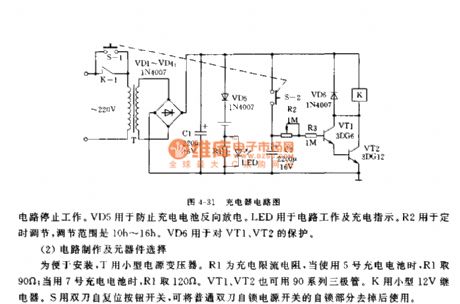
Operating principle:
The circuit is as shown in figure 4-31, the whole circuit is composed of rectifier and filter circuit, the constant current charging circuit, the timing control circuit, because the timer's accuracy requirement is not high, so we can use the simple rectification circuit. The charging part uses the constant current charging mode, the circuit is simple and the effect is good. The timing part uses the composite tube operating mode.
When you press S, the 220V AC current is reduced, rectified and filted by the T, VD1-VD4 and C1, so we get the 12V DC. The 12V DC not only supplies the charging voltage to the VD5, R1 and LED, but also charges C2 through S2.
(View)
View full Circuit Diagram | Comments | Reading(746)
Motorola 168VA cell phone car charger
Published:2011/7/14 21:04:00 Author:TaoXi | Keyword: Motorola, cell phone, car, charger

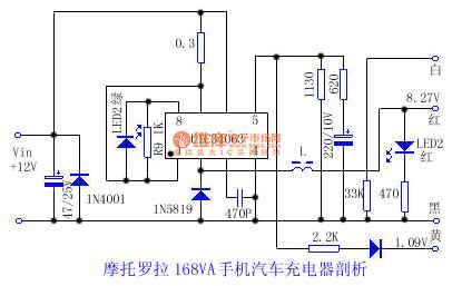
There is one kind of car charger that is suitable for the Motorola 168VA cell phone, it's volume is small and exquisite, and it can directly plug into the car cigarette lighter socket. But it has no circuit diagram, so the maintenance is inconvenience. The measured circuit is as shown in the figure for reference.
The UTC34063 is the 8-pin dual-row DIP IC, it is the single chip buck-boost DC converter control IC. This IC has the temperature compensator, the comparator, the high current output switch. The oscillation frequency is 100KHz. The measured data is as shown in the table.
Pin .....Resistance ......Voltage(V)......Red measurement(KΩ) Black measurement(KΩ) 1 ......4.1 ......8.2 .......12 2 ......0.8...... 7.8...... 8.28 3 ......5.8 ......22 .......0.65 4 .......0 ........0......... 0 5 .......1........ 1 .......1.26 6 ......4.2 ......8.2 .......12 7 ......4.2 ......8.2 .......12 8 .......5........ 10 ......10.6
(View)
View full Circuit Diagram | Comments | Reading(2141)
Pulse type automatic charger circuit (3)
Published:2011/7/14 21:17:00 Author:TaoXi | Keyword: Pulse type, automatic, charger circuit
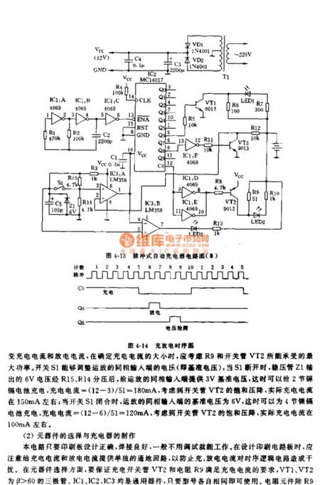
Operating principle:
The circuit principle diagram of this charger is as shown in figure 4-13. The power transformer T1 changes the 220V AC into the 9V AC, and this 9V AC is rectified by VD1 and VD2, then it is filted by C3 to supply the 12V DC voltage to the charger, the capacitance C4 can be used in filtering. The oscillator is composed of the IC1:A, IC2:B and the external components, IC1:C is the buffer stage of the oscillator, the output of IC1:C supplies the clock pulse for the counter IC2. IC2 is the decimal counter, it can be used to control the charging time and discharging time of the charger, and it counts the lower edge of the clock pulse. The charging and discharging timing sequence is as shown in figure 4-14.
(View)
View full Circuit Diagram | Comments | Reading(701)
Pulse type automatic charger circuit (2)
Published:2011/7/14 21:29:00 Author:TaoXi | Keyword: Pulse type, automati, charger
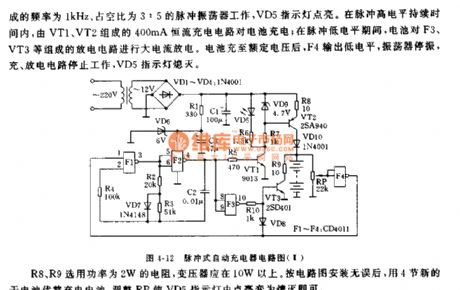
The pulse type automatic charger that is composed of the single chip manifold block CD4011 and a few external components, it can supply the large current pulse type charging and discharging for four Nickel cadmium batteries with the charge-discharge ratio of 7:2, and when the battery is full, it will stop charging automaticly. The features of this circit is simple and practical.
As the figure 4-12 shows, when the circuit is operating, the input port F4 has the low level, the high level of the inverted output controls the pulse oscillator with the frequency of 1 kHz and duly ratio of 3:5. The VD5 indicator lamp turns on.
(View)
View full Circuit Diagram | Comments | Reading(702)
Pulse type automatic charger (1)
Published:2011/7/14 21:53:00 Author:TaoXi | Keyword: Pulse type, automatic charger
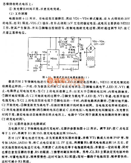
Operating principle:
The circuit is as shown in figure 4-11, the city electricity is reduced by the transformer and is bridge-type rectified by VD1-VD4, so point A gets the 20V voltage, this voltage is limited by R1, stabilized by VD5 and C1, so point B gets the 14V stabe voltage, this voltage is supplied to NE555, so the NE555 produces the oscillation and outputs the control signal from pin-3 to control the charging process, by adjusting RP, we can establish the reference potential at C point.
IF you want to charge the 12V storage battery, you need to improve the transformer capacity, and the VT1 need to use the high power PNP transistor such as the 3AD6, 3AD30. The electric potential of point C is about 12.3V.
(View)
View full Circuit Diagram | Comments | Reading(652)
Lithium ion battery charger circuit (3)
Published:2011/7/14 22:36:00 Author:TaoXi | Keyword: Lithium ion battery, charger
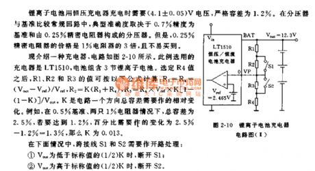
When the lithium ion battery is charging with the constant voltage charger, you need to use the 4.1+/-0.05V voltage, the strict tolerance is 1.2%. In the voltage divider and the benchmark comparison conventional circuit, the typical accuracy depends on the voltage divider which is composed of the electrical resistor with the 0.7% accuracy and 0.25% precision. The price of the 0.25% precision resistor is three times of the 1% precision resistor, and it is hard to find.
Here we introduce one kind of charger, the circuit is as shown in figure 2-10. The charger is LT1510, the battery pack has three Lithium ion batteries. If you choose the value of R4, the values of R1,R2,R3 can be calculated by the formula.
(View)
View full Circuit Diagram | Comments | Reading(767)
Lithium ion battery charger circuit (2)
Published:2011/7/14 23:02:00 Author:TaoXi | Keyword: Lithium ion battery, charger circuit
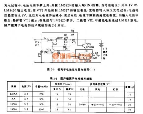
The simplest Lithium ion battery charger circuit is as shown in figure 2-9. This charger uses the lithium ion battery charging controller LM3420-8.4, it can charge two series lithium-ion battery groups. When the voltage of the battery group is lower than 8.4V, the output port of LM3420 has no output current, the transistor VT2 cuts off, so the adjustable voltage-regulator tube LM317 outputs the constant current. The rated output current of the LM317 is 1.5A, if you need the larger charging current, you can use LM350 or LM338.
In the charging process, the battery voltage rises and it is detected by the output port of LM3420. When the battery voltage is 8.4V, the LM3420 outputs the current to make the VT2 control the output voltage of LM317.
(View)
View full Circuit Diagram | Comments | Reading(2557)
Concise parallel automatic charger circuit
Published:2011/7/15 0:41:00 Author:TaoXi | Keyword: Concise, parallel, automatic, charger
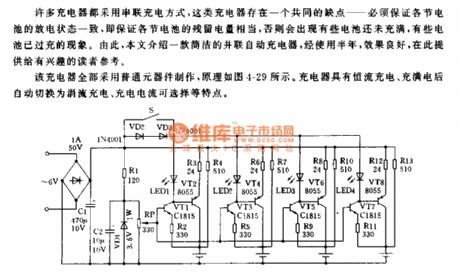
A lot of chargers use the series charging mode, these chargers have a common shortcoming--you need to guarantee that every battery has the same residual power, otherwise some batteries are overcharging but some batteries are insufficient charging. So this artical introduces one kind of concise parallel automatic charger which has good effect.
This charger is composed of the common components, the principle is as shown in figure 4-29. The charger has the features of constant current charging, automatic switchover (trickle charge), and the optional charging current.
(View)
View full Circuit Diagram | Comments | Reading(696)
| Pages:188/291 At 20181182183184185186187188189190191192193194195196197198199200Under 20 |
Circuit Categories
power supply circuit
Amplifier Circuit
Basic Circuit
LED and Light Circuit
Sensor Circuit
Signal Processing
Electrical Equipment Circuit
Control Circuit
Remote Control Circuit
A/D-D/A Converter Circuit
Audio Circuit
Measuring and Test Circuit
Communication Circuit
Computer-Related Circuit
555 Circuit
Automotive Circuit
Repairing Circuit