
Index 198
AAT3680 lithium battery linear charging integrated circuit
Published:2011/7/3 21:09:00 Author:Christina | Keyword: lithium battery, linear charging, integrated circuit

The AAT3680 is designed as one kind of lithium battery linear charging integrated circuit that can be used in cellphone, PDA, digital camera and the desktop charger.
1.Features
The charging system which is composed of the AT3680 has the function of charging voltage and charging current adjustment, also it sets the two times inrush current charging function, there is a pin to control the two times inrush current.
2.Pin functions and data
The AAT3680 has eight pins and it has three kinds of packages: MSOP、TSSOP or SOP, the pin-5 of the SOP and TSSOP has the same function and arrangement.
Table 1 The pin functions and data of the AAT3680
3.Typical application circuit
The typical application circuit of the AAT3680 is as shown in figure 1.
Table 2 The five kinds of charging state and display situations
(View)
View full Circuit Diagram | Comments | Reading(659)
multipath supply output circuit
Published:2011/6/28 6:39:00 Author:chopper | Keyword: multipath supply, output circuit
The picture is a multipath supply output circuit,it will output three values of voltage like +UCC and ±UA.In the circuit,point A is the reference earthing point of positive-negative double supply;point B is the reference earthing point of positive power supply.① is the earth lead among reference potentials; ② is the reference earth lead of the regulator.
(View)
View full Circuit Diagram | Comments | Reading(592)
Samsung 173B LCD DC/DC Convertor Circuit
Published:2011/7/1 0:27:00 Author:Joyce | Keyword: Samsung , 173B , LCD , DC/DC , Convertor
Samsung 173B LCD DC/DC convertor circuit is shown as follows.
Samsung 173B LCD DC/DC Convertor Circuit (View)
View full Circuit Diagram | Comments | Reading(604)
CD4541 nickel-cadmium battery automatic charger circuit
Published:2011/6/20 6:36:00 Author:chopper | Keyword: nickel-cadmium battery, automatic charger circuit
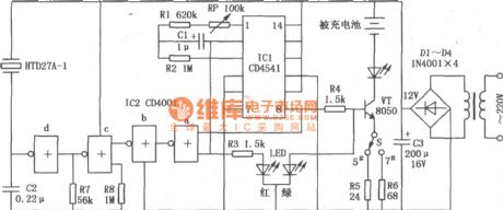
This circuit is designed for number 5,number 7 nickel-cadmium battery especially,and it has features of automatic charging and constant-current charging.The circuit is shown as follows.The circuit will begin to run as soon as the power supply is connected.The inner counter is responsible for counting the oscillator to a full count,and at this moment,the output level of foot ⑧ of IC1 will return to stop counting.For instance,foot ⑩ is connected with high level,and the food ⑧ will return when the counter is full,then it will count again,and return when it is full,and so on and so on.
(View)
View full Circuit Diagram | Comments | Reading(4244)
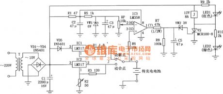
cellphone lithium ion battery charger circuit of LM317
Published:2011/6/20 6:37:00 Author:chopper | Keyword: cellphone, lithium ion battery, charger circuit
View full Circuit Diagram | Comments | Reading(4181)
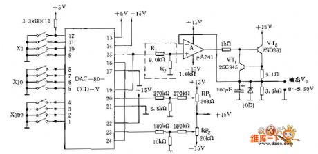
Numerical control reference voltage source cirucit diagram with 0~9.99V output voltage
Published:2011/6/24 8:24:00 Author:Nicole | Keyword: numerical control, reference voltage source, 0~9.99V output voltage
View full Circuit Diagram | Comments | Reading(539)
The circuit of the 3-phase motor powered by the single phase
Published:2011/7/1 22:30:00 Author:Borg | Keyword: 3-phase motor, single phase
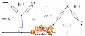
To run a 3-phase motor with a single power supply, we just need a proper phase drifting capacitor, the methods are as follows: for the motor of star connection, whose connection is shown in figure 1; for the motor of triangular connection, the connection is shown in figure 2. According to the practice, the value of the volume in the phase-drifting capacitor should be equal to the product of 0.07 and the motor power, for example, the power of the motor is 150W, and the volume of the capacitor is equal to 0.07 x 150=10.5uF, so the need can be met by connecting two sunlight lamps (4.75μF) in parallel way.
(View)
View full Circuit Diagram | Comments | Reading(2227)
The self-made temporary power supply circuit
Published:2011/7/1 22:39:00 Author:Borg | Keyword: self-made, temporary power supply
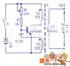
1. The circuit principle The transistor V, the coils of N1 and N2 of transformer T and capacitor C compose the transformer coupling LC oscillator circuit. The potentiometer RP and resistor R provides with a bias current of the oscillator. 2. Elements selection V is adopted with 3DD59A, R is the 1/4W ordinary resistor, C is 0.22μF/50V, the transformer is self-made, N1 and N2 are the 0.9mm covered wire, the N3 coil is the 0.67mm covered wire, the coil frame can be made by the hard paper board of 1mm, the magnet would better be the ferrite of U or loop shape, if not, it can be replaced by the silicon sheet of E or F shape.
(View)
View full Circuit Diagram | Comments | Reading(809)
Intelligent charging system schematic block circuit
Published:2011/7/2 3:09:00 Author:John | Keyword: charging system, schematic block
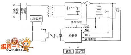
The chip is the three-terminal isolated PWM monolithic switching power supply integrated circuit, which is produced by the United States Powergration. It integrates the PWM IC and FET in the same chip, thus occupying all the require functionality of the PWM switching power supply. High-frequency transformer is able to isolate the output termination from the grid completely. This also can achieve the isolated single-chip switching power supply integration of a non-frequency transformer. The entire circuit is with a wide range of output power, low cost, high degree integration and simple circuit design and other advantages.
(View)
View full Circuit Diagram | Comments | Reading(1074)
ST6210 battery charger circuit
Published:2011/7/2 2:50:00 Author:John | Keyword: battery charger
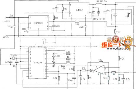
Currently, the environmentally nickel-metal hydride batteries will gradually replace nickel-cadmium batteries. Therefore, the compatible chargers for nickel cadmium and Ni-MH batteries are needed. In this case, common monitoring methods for nickel-cadmium batteries are no longer suitable for charging nickel-metal hydride batteries. The termination method for battery charger is based on detecting the curve inflection point of battery voltage. The detection for the turning point of nickel-metal hydride batteries is not only allows the compatibility for the charger of nickel-metal hydride batteries and nickel-cadmium batteries. The detection can also extend the service life of nickel-cadmium batteries. The compatible charger can use a 8-bit microcontroller (MCU, such as ST's ST6210) for being controled.
(View)
View full Circuit Diagram | Comments | Reading(1748)
MAX1501 charger circuit
Published:2011/7/2 1:50:00 Author:John | Keyword: charger
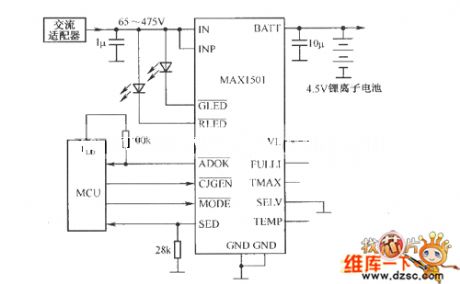
MAX1501 is a new generation of rechargeable chip. MAX1501 is used to simplify the design of the charger. MAX1501 can be set as the single cell Li-Ion battery charging controller and can also be set as charging controller with three nickel cadmium batteries and Nickel metal hydride battery in series. MAX1501 charger circuit is as shown.
(View)
View full Circuit Diagram | Comments | Reading(1130)
The simple touching switch
Published:2011/7/2 3:27:00 Author:Borg | Keyword: simple touching switch
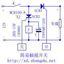
In experiments, the writer found that the single-way SCR (MCR100-8) control pole can be conducted by hand touch without any forward voltage. Therefore, the writer designed a simple touching switch, whose circuit is shown in the figure.
Just by touching the metal chip, SCR1 is conducting, so the load is getting power and working; by touching the metal chip, the switch is off and SCR2 is conducting, the relay 1 is getting power and working, K is cut off, the load loses power, after SCR2 is broken down, the capacitor is discharging power to relay J, which keeps the relay close about 4s. (View)
View full Circuit Diagram | Comments | Reading(963)
The simple 2-terminal source free electric energy saving switch circuit
Published:2011/7/2 3:40:00 Author:Borg | Keyword: 2-terminal, source free, energy saving switch
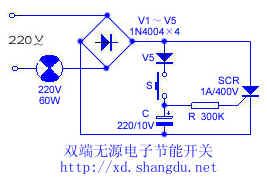
By pressing S, the 220V AC current is charging C through V5 after it is rectified, when the voltage on the capacitor is higher than the trigger voltage of the single way SCR control pole, the SCR is triggered and conducting, and the bulb is lighting. After S is released, the electricity of the capacitor is discharging through resistor R, which keeps the single-way SCR conducting, when the time reaches the set time (the lighting time of this circuit parameter is from 1 to 2min), the single-way SCR is cut off when the current is lower than the maintaining current, the bulb is cut off. (View)
View full Circuit Diagram | Comments | Reading(3614)
TWL2213 Lithium ion battery charging process circuit
Published:2011/7/1 1:25:00 Author:TaoXi | Keyword: Lithium ion battery, charging, process
View full Circuit Diagram | Comments | Reading(570)
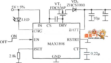
MAXl898 single Li+ battery linear charger circuit
Published:2011/7/1 1:33:00 Author:TaoXi | Keyword: single, Li+ battery, linear charger
View full Circuit Diagram | Comments | Reading(593)
Charger circuit composed of the BQ2000
Published:2011/7/1 0:52:00 Author:TaoXi | Keyword: Charger circuit
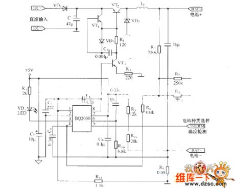
View full Circuit Diagram | Comments | Reading(1748)
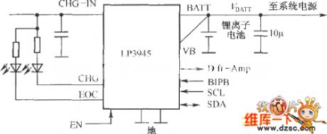
Charging circuit composed of the LP3945
Published:2011/7/1 0:56:00 Author:TaoXi | Keyword: Charging circuit
View full Circuit Diagram | Comments | Reading(558)
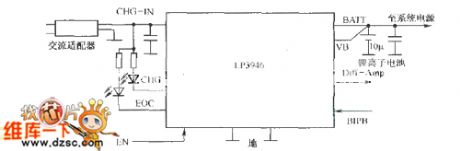
Independent charger composed of the LP3945
Published:2011/7/1 1:16:00 Author:TaoXi | Keyword: Independent charger
View full Circuit Diagram | Comments | Reading(484)
positive-negative double supply circuit
Published:2011/6/28 6:31:00 Author:chopper | Keyword: positive-negative, double supply circuit
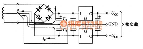
The picture is a positive-negative double supply circuit which is usually adopted in the analog circuit.It is a power sipply circuit formed by tapped full-wave rectification and three terminal regulator.The ground of smoothing capacity C1,C2 and regulator is connected to A point on the tapped landline of transfer. Point A is a reference potential.The supply output will not be effected by the smoothing current of C1 and C2.
(View)
View full Circuit Diagram | Comments | Reading(563)
Limited current circuit with transistor
Published:2011/6/27 21:44:00 Author:chopper | Keyword: Limited current circuit, transistor
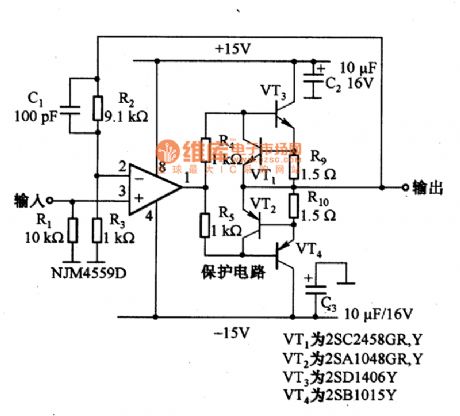
The picture is a limited current circuit with operational amplifier.In the circuit,R9 and R10 are used to detect output current.When the voltage drop is more than 0.6V,VT1 and VT2 will stop to cut off current.In this case,the current of VT3 and VT4 is limited within 400mA. (View)
View full Circuit Diagram | Comments | Reading(1426)
| Pages:198/291 At 20181182183184185186187188189190191192193194195196197198199200Under 20 |
Circuit Categories
power supply circuit
Amplifier Circuit
Basic Circuit
LED and Light Circuit
Sensor Circuit
Signal Processing
Electrical Equipment Circuit
Control Circuit
Remote Control Circuit
A/D-D/A Converter Circuit
Audio Circuit
Measuring and Test Circuit
Communication Circuit
Computer-Related Circuit
555 Circuit
Automotive Circuit
Repairing Circuit