
Index 190
Reliable performance 20V, 2A regulated power supply circuit diagram
Published:2011/7/17 1:06:00 Author:nelly | Keyword: 2A regulated power supply, 20V regulated power supply
View full Circuit Diagram | Comments | Reading(1152)
0 ~ ± 30V, 1.5A power supply circuit diagram composed of LM317
Published:2011/5/13 4:01:00 Author:Ecco | Keyword: 0, ± 30V , 1.5A , power supply
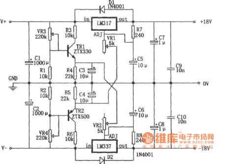
0 ~ ± 30V, 1.5A power supply circuit diagram composed of LM317 is shown as the chart. The features of the power supply can be seen from the figure, its positive and negative output voltage can be transferred to the minimum 0V. LM317 (LM337) can only be transferred to the 1.25 (-1.25) V under normal circumstances, but the adjustment end of the adjustable three-terminal is added the appropriate amount of reverse bias, the output voltage can be changed to zero by negative voltage of TH2 emitter being connected to VR1, and the positive voltage of TH1 emitter being connected to VR2. (View)
View full Circuit Diagram | Comments | Reading(5348)
The 1.25~27V adjustable power supply circuit diagram composed of μA723 high definition IC
Published:2011/5/11 4:14:00 Author:Ecco | Keyword: 1.25~27V , adjustable , power supply, high definition , IC
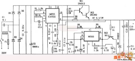
This power supply circuitis composed ofthe high definition integrated circuit μ A723 . The characteristics are as below: (1)The output voltage is adjustablein the range of 1.25~27 V. (2)Having current limiting safeguard function. While output current ≥ 6.5 A , the internal current limitingcircuit of μ A723turns onto protect voltage regulator. (3)The voltage stabilizes well, the currentis inthe range of0~4.5 A, output voltage changes 0.03 V.(4)Having short circuit indicating function.The short circuit indication oscillatoris composed of555 integrated circuit, when the output voltage exists, 555does notoscillation, LED is often bright, when there is no output voltage(output port short circuit), 555 generates oscillation, LED is shining with the frequencyin 0.5~1 Hzs. (View)
View full Circuit Diagram | Comments | Reading(1453)
35w set -top -box switching supply circuit diagram
Published:2011/5/11 4:16:00 Author:Ecco | Keyword: 35w supply , set -top -box switching
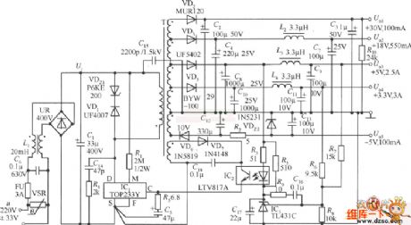
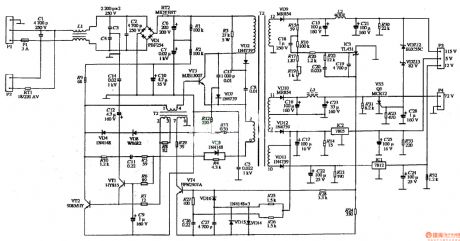
The 5 roads voltage of 35w set -top -box switching supply circuit diagram are distinguished as: Uo1(+30 V, 100 ma), Uo2(+18 V, 550 ma), Uo3(+5 V, 2.5 A), Uo4(+3.3 V, 3 A), Uo5.(-5 V, 100 ma). Among them, +5 V and + 3.3 Vare main output, the rest of allare assisting output. When the swaping input voltage u=220(1 ± 15%) V, the total output power ofswitch reaches 38.5 W, if adopting breadth range voltage input(u=85~265 V), the total outputreduces 25 W. It can be used as the power supply of box(Set ― top Box), video recorder(VCR) , shoot video recorder(CVCR) and DVD machine. The power supply of machine set -top -box switching is higher than 77%, and it has the function of undervoltage and overvoltage protection. (View)
View full Circuit Diagram | Comments | Reading(5555)
The power supply circuit of CTX-C15 VGA high resolution color display
Published:2011/5/12 2:20:00 Author:Ecco | Keyword: VGA, high resolution , color , display, power supply
View full Circuit Diagram | Comments | Reading(809)
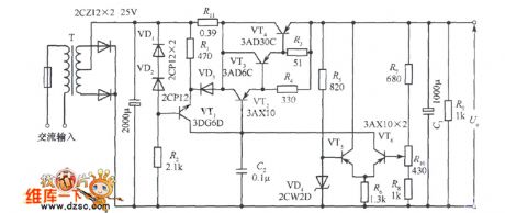
DC regulated power supply circuit diagram with 2A output
Published:2011/5/17 4:01:00 Author:Ecco | Keyword: DC , regulated power supply , 2A output
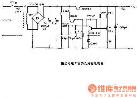
Thisis theDC regulated power supply with constant output in 2A. It is suitable for adjusting voltage of the electrical equipments and TV with 2A current and 12V voltage. The chart shows the circuit:
(View)
View full Circuit Diagram | Comments | Reading(2674)
LED power supply voltage multiplier circuit diagram
Published:2011/5/17 4:11:00 Author:Ecco | Keyword: LED, power supply, voltage multiplier
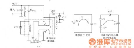
The power supply voltage multiplier conversion circuit is shown as the chart. In electronic circuit design, some amplifiers require low current and high voltage, they can use flashing LED and few components to make a DC voltage multiplier conversion circuit. In the Figure (a), it uses capacitors C1, C2 to store charge, the flashing LED's own oscillations can drive relay switch conversion, and the supply voltage and C1 are continuously superimposed, and it will get a twice supply voltage on C2, the output current is about 10mA. Relay uses 6V or 30mA, Figure (b) is the multiplier principle diagram.
(View)
View full Circuit Diagram | Comments | Reading(802)
KA431--the precise reference regulated integrated circuit
Published:2011/7/13 19:52:00 Author:Borg | Keyword: precise reference, integrated circuit
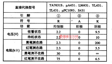
KA431 is a precise reference regulated integrated circuit produced by Samsung, which is widely used in the switch power supply circuit of the color TV, stereo, air-conditioner, disc player and other electric appliances.1.function featuresKA431 contains the sampling fault amplifier circuit, control circuit and other additional circuits.2.pin functions and dataKA431 is in the 3-pin in-line package, whose pin functions and data are listed in table 1-1, and all the data are from the tests on Haier BGBTV-29FA, 29TA, 29F18 and so on.
(View)
View full Circuit Diagram | Comments | Reading(868)
CM6800 and CM6801--the single chip power supply control integrated circuit
Published:2011/7/12 22:35:00 Author:Borg | Keyword: single chip, power supply, integrated circuit
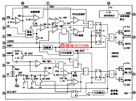
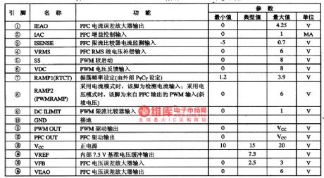
CM6800 and CM6801 are the single chip PFC+PWM control integrated circuit produced by CMC Corp., the USA, which is widely used in PC power supply, air-conditioner, large screen color TV, monitor, UPS and AC adapter, etc.1.function featuresCM6800 and CM6801 have functions of over-voltage protection, over-current protection and over-heat protection, the power factor is close to 1. The PWM in them is added with the current limitation function; 23VBi-coms process has the synchronized leading edge PFC and rear edge PWM, which provides with high switch ratio for rising the reaction speed; the fault amplifier works in a low starting circuit and low working current.
(View)
View full Circuit Diagram | Comments | Reading(3984)
K6XH-the communication single chip computer integrated circuit
Published:2011/7/13 23:04:00 Author:Borg | Keyword: communication, single chip
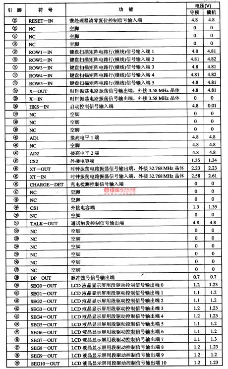
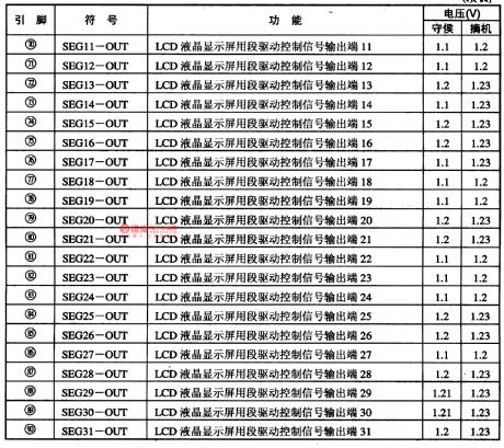
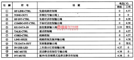
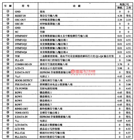
K6XH is a communication single chip computer integrated circuit, which is used in the main control circuit of phones.1.function featuresK6XH contains the pulse/dual audio compatible dialing circuit, keypad switch encoding/decoding circuit, LCD drive control circuit, buzzer drive control circuit, mute control circuit, charge detection circuit, communication control circuit, clock oscillating circuit and other function circuits.2.pin functions and dataK6XH is in 90-pin package.
(View)
View full Circuit Diagram | Comments | Reading(659)
ICL7106-the A/D converter integrated circuit
Published:2011/7/13 22:46:00 Author:Borg | Keyword: A/D converter
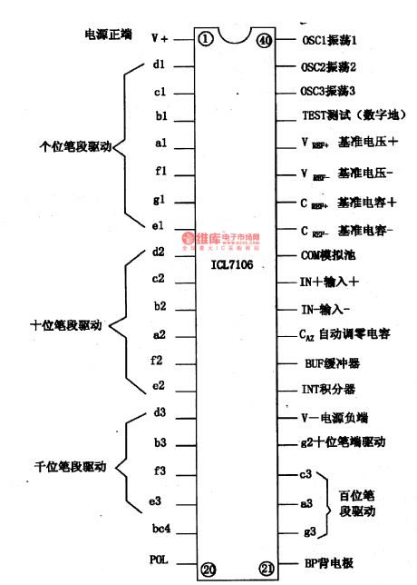

ICL7106 is an A/D converter integrated circuit, which is widely used in 3 1/2 digital multimeters (such as DT830 and DT890).1.function featuresICL7106 contains the clock oscillating circuit, display digit screen drive control circuit, A/D converter circuit, and other additional function circuits.2.pin functions and dataICL7106 is in the 40-pin dual line package, whose pin arrangement and functions are shown in figure 1-1, the actually measured resistances are listed in table 1-1.Notes: ICL7106 can be replaced by TSC7106 directly.
(View)
View full Circuit Diagram | Comments | Reading(1652)
J80-1A56-the communication single chip microcomputer circuit
Published:2011/7/13 20:58:00 Author:Borg | Keyword: communication single chip, microcomputer circuit
1.function introduction J80-1A56 contains the pulse/dual audio compatible dialing circuit, the call display signal process circuit of FSK/DTMF dual-system, wireless emitting and receiving signal control circuit, keypad switch encoding/decoding circuit, LCD display connector circuit, storage connector circuit, mute control circuit, indicator drive control circuit, receiving signal field force detection circuit, ringing detection and other control circuits, etc. 3.pin functions and dataJ80-1A56 is in 44-pin package, whose pin functions and data are listed in table 1-1.
(View)
View full Circuit Diagram | Comments | Reading(604)
Automatic nickel cadmium battery charger circuit
Published:2011/7/14 2:31:00 Author:TaoXi | Keyword: Automatic, nickel cadmium battery, charger
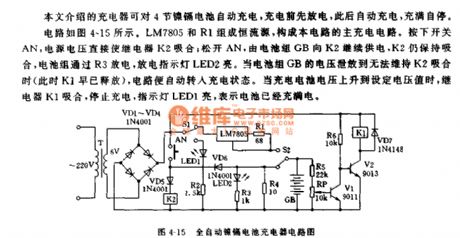
The circuit is as shown in figure 4-15. The constant current source is composed of the LM7805 and R1. IF you press the switch AN, the power supply voltage will make the relay K2 close; if you loosen the AN, the battery pack GB still supplies the power to the K2, so K2 is also in the closing state, the battery pack discharges through R3, the discharge indicator light LED2 turns on. When the battery pack GB's voltage can not maintain the closing of K2, the circuit will get into the charging state automaticly. When the rechargeable battery voltage increases to the set voltage, the relay K closes to stop charging, the indicator light LED1 turns on, this means the battery is full.
Figure4-15 Automatic nickel cadmium battery charger circuit
(View)
View full Circuit Diagram | Comments | Reading(1027)
The principle diagram of DPCA-Fukang DC7140 circuit
Published:2011/7/11 22:48:00 Author:Borg | Keyword: principle diagram, DPCA-Fukang
The principle diagram of DPCA-Fukang DC7140 circuit (View)
View full Circuit Diagram | Comments | Reading(594)
The principle diagram of DPCA-Fukang DC7140 circuit (2)
Published:2011/7/11 22:49:00 Author:Borg | Keyword: principle diagram, DPCA-Fukang
The principle diagram of DPCA-Fukang DC7140 circuit (2) (View)
View full Circuit Diagram | Comments | Reading(580)
KW8889-the communication single chip microcomputer integrated circuit
Published:2011/7/12 3:03:00 Author:Borg | Keyword: communication, single chip, microcomputer, integrated circuit
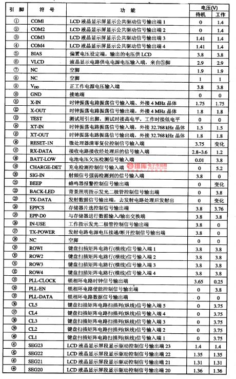
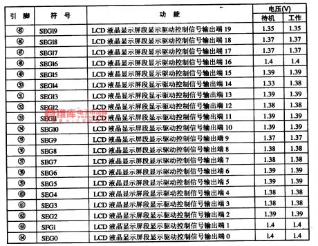
KW8889 is a communication single chip microcomputer integrated circuit, which is widely used in caller display telephones.1.function introductionKW8889 contains the wireless emitting and receiving control circuit, key switch encoding circuit, RF intensity detection circuit, LCD display drive control circuit, storage connector circuit, background lighting indication control circuit, PLL circuit, 2 teams of clock oscillating circuit, charge detection and battery low voltage detection circuit, buzzer drive control circuit and so on.2.pin functions and data
(View)
View full Circuit Diagram | Comments | Reading(660)
The diagram reading illustration of DPCA-Fukang DC7140
Published:2011/7/11 23:11:00 Author:Borg | Keyword: illustration, DPCA-Fukang
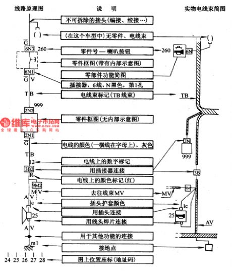
Figure: The diagram reading illustration of DPCA-Fukang DC7140 (1) the two letters on the two side of the wire indicate the symbols of the wire bundles, the figured T1B means the wire is in TB wire bundle, other bundles, such as PB, MT, AV, CP, FR and MV, all the them are the names of the car wire. (2) the wire colors are represented by the letters and the transverse lines near the connector, of which the letters with lines on them means basic color, the other letter means the stripe color on the wire, which are the differences. (View)
View full Circuit Diagram | Comments | Reading(592)
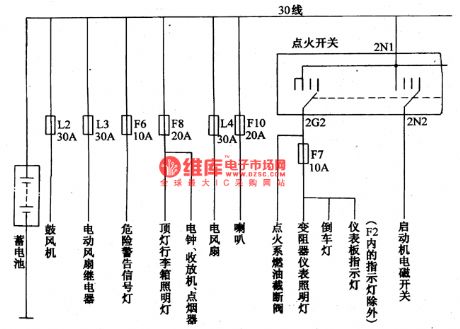
The fuse circuit of DPCA-Fukang DC7140 car
Published:2011/7/12 0:50:00 Author:Borg | Keyword: fuse circuit, DPCA-Fukang

figure: The fuse circuit of DPCA-Fukang DC7140 car (View)
View full Circuit Diagram | Comments | Reading(561)
Minitype lead-acid storage battery adjustable charger circuit
Published:2011/7/13 21:19:00 Author:TaoXi | Keyword: Minitype, lead-acid, storage battery, adjustable charger
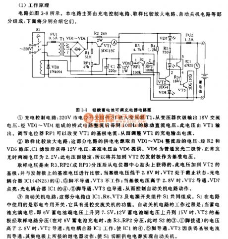
Operating principle:
The circuit is as shown in the figure 3-8. This circuit is composed of the charging control circuit, the sample comparison amplifier circuit, the automatic shutdown circuit.
The charging control circuit: the 220V city electricity is transmitted into the transformer T1 through the switching component S1, and the transformer secondary stage outputs the 18V AC voltage, this voltage is rectified by the bridge circuit which is composed of the VD1-VD4, so we get the 100Hz pulsating DC voltage.
The sample comparison amplifier circuit: the power supply is the voltage which is rectified by VD1-VD4, and it is stabilized by R2 and VD5, then it is filted by C1 to get the 12V voltage, the benchmark voltage is supplied by VD6.
(View)
View full Circuit Diagram | Comments | Reading(806)
Four-channel single battery independent charging automatic charger circuit
Published:2011/7/13 21:54:00 Author:TaoXi | Keyword: Four-channel, single battery, independent charging, automatic charger
The feature of this charger is that it can independently charge the four-channel single battery, each channel has a automatic control charging circuit, and four red LEDs indicate the charging status respectively.
The city electricity is reduced by the transformer T, one channel is rectified by VD1, then it is filted by R1 and C1, stabilized by VD4 to output the 4.6V stable voltage through the R2, C2 secondary filter, this voltage is used by four channels of control circuit; another channel is rectified by VD2 to supply the four channels of half-wave pulse current for the charging. In the figure there is only one channel of control circuit, the other channels are the same. The control manifold uses the quad comparator LM339.
(View)
View full Circuit Diagram | Comments | Reading(740)
| Pages:190/291 At 20181182183184185186187188189190191192193194195196197198199200Under 20 |
Circuit Categories
power supply circuit
Amplifier Circuit
Basic Circuit
LED and Light Circuit
Sensor Circuit
Signal Processing
Electrical Equipment Circuit
Control Circuit
Remote Control Circuit
A/D-D/A Converter Circuit
Audio Circuit
Measuring and Test Circuit
Communication Circuit
Computer-Related Circuit
555 Circuit
Automotive Circuit
Repairing Circuit