
Index 181
Motorcycle Charging Circuit
Published:2011/7/14 6:05:00 Author:Sue | Keyword: Motorcycle, Charging
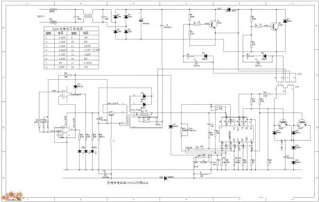
When it is being charged, the voltage will rise from 37.9v to 44.4v. (View)
View full Circuit Diagram | Comments | Reading(1168)
Wide Input Range Voltage Stabilizing Circuit
Published:2011/7/18 6:08:00 Author:Sue | Keyword: Wide, Input Range, Voltage Stabilizing
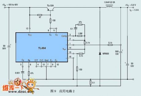
Figure 9 application circuit 2 (View)
View full Circuit Diagram | Comments | Reading(953)
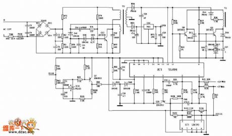
High Efficiency Charging Circuit
Published:2011/7/18 7:29:00 Author:Sue | Keyword: High Efficiency, Charging
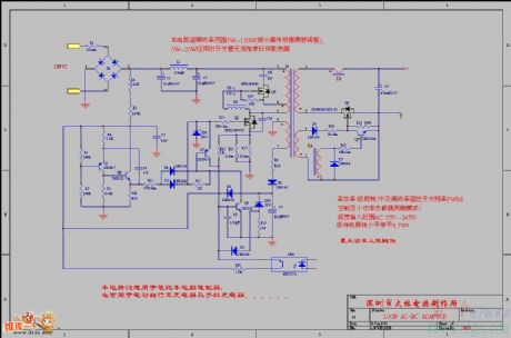
The circuit can be used in power range of 5W-150W(some components have to be adjusted). When it's between 5W-25W, there is no need to put any radiatoron the switch tube.
The circuit is assumed to be used in laptop adapter. It can also be used in electric bicycle's charger and mobile phone's charger. (View)
View full Circuit Diagram | Comments | Reading(962)
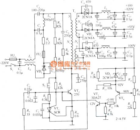
3000VA Inverter Power Circuit
Published:2011/7/14 7:12:00 Author:Sue | Keyword: 3000VA, Inverter

View full Circuit Diagram | Comments | Reading(3804)
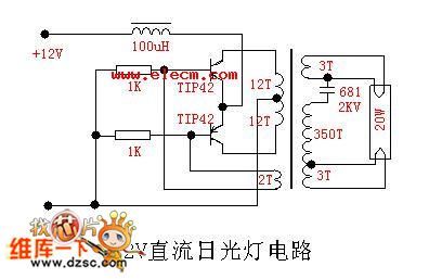
12V Direct Current Fluorescent Lamp Circuit
Published:2011/7/15 6:02:00 Author:Sue | Keyword: Direct Current, Fluorescent Lamp
View full Circuit Diagram | Comments | Reading(2522)
ATX Power Circuit
Published:2011/7/15 5:56:00 Author:Sue | Keyword: Power
View full Circuit Diagram | Comments | Reading(1992)
555 Illuminations Group Centralized Rectification and Starting Circuit
Published:2011/7/20 5:38:00 Author:Sue | Keyword: Illuminations Group, Centralized Rectification, Starting Circuit
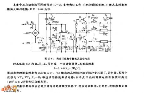
The centralized rectification and starting circuit can drive 10-20 illuminations to work at the same time. As seen in figure 17-64, it consists of voltage reduction, rectification, separate-excited high frequency push-pull oscillation.
Time-base circuit 555 and R2,R3,C3 compose a multivibrator and its oscillate frequency is f=1.44(R2+2R3)C3. The parameter in the figure has an oscillate frequency of about 25kHz. 555's output high frequency pulse will be put on pulse voltage transformer's primary stage. Its two secondary stages and VT1,VT2,R4-R7 will compose push-pull drive circuit. The high frequency voltage's effective valueon the middle point O can reach as high as 140v which will turn on the illuminations.
The criticalthing that can realise centralized rectification and starting are the high frequency voltage transformer T1's design and production. Its primary and secondary parameters will be shown in figure 17-64. (View)
View full Circuit Diagram | Comments | Reading(641)
The car engine tachometer (1)
Published:2011/7/23 8:31:00 Author:qqtang | Keyword: engine tachometer
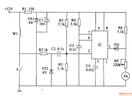
The working principle of the circuit The car engine tachometer consists of the 9V regulator circuit, single steady trigger circuit and current indicating circuit, see as figure 7-73.
The +9V voltage stabilizing circuit consists of the resistor R1, regulator diode VS1 and filter capacitor C1. The single steady trigger consists of the time-based integrated circuit IC, resistors R2-R5, capacitors C2-C4 and regulated diode VS2. The current indicating circuit consists of the diode VD, resistor R6, potentiometer RP and ampere meter PA. (View)
View full Circuit Diagram | Comments | Reading(2323)
The car engine tachometer (2)
Published:2011/7/23 8:40:00 Author:qqtang | Keyword: engine tachometer

The working principle of the circuit The car engine tachometer consists of the relaxation oscillator, integrating circuit, comparing amplifier and ampere meter drive circuit, see as figure 7-74.
The relaxation oscillator circuit consists of the resistors R1-R3, capacitor C1 and single knot transistor VU. The integrating circuit consists of the capacitor C3 and resistors (R4, R5). The comparing amplifier consists of the op-amp integrated circuit IC, resistors R6-R10, capacitor C2, diodes VD1-VD3 and so on. (View)
View full Circuit Diagram | Comments | Reading(880)
The LED car voltmeter (1)
Published:2011/7/23 20:00:00 Author:qqtang | Keyword: car voltmeter
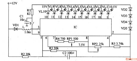
Here is to introduce the LED car voltmeter which is made of the LM3914 display drive integrated circuit and LED, the display voltage range is 10.5V-15v, it can be used vehicles of 12V battery.The working principle of the circuit The LED car voltmeter consists of the display drive integrated circuit IC, point/line display mode selection switch S, resistors R1-R5, potentiometers of RP1 and RP2, diodes VD1-VD5, capacitors of C1 and C2, LED VL1-VL10, see as figure 7-75.
(View)
View full Circuit Diagram | Comments | Reading(3137)
The LED car voltmeter (2)
Published:2011/7/23 20:04:00 Author:qqtang | Keyword: car voltmeter
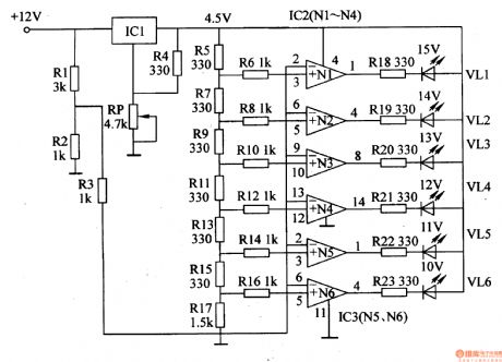
Here is to introduce the LED car voltmeter which is made of the op-amp LM312 and LED, it can display 6 gears of voltages, 10-15V, each gear is 1V.The working principle of the circuit The LED car voltmeter consists of the regulator circuit, Vref circuit, sampling voltage circuit and LED display drive circuit,see as figure 7-76.
The regulator circuit consists of the 3-terminal regulator circuit IC, potentiometer RP and resistor R4.
(View)
View full Circuit Diagram | Comments | Reading(4312)
The LED car voltmeter (3)
Published:2011/7/23 20:12:00 Author:qqtang | Keyword: car voltmeter
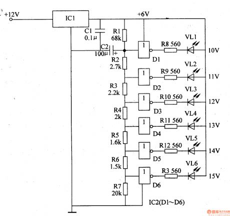
The working principle of the circuit The LED car voltmeter consists of the filter circuit, voltage distribution filter circuit, voltage amplifier circuit and LED display circuit, see as figure 7-77.
The regulator filter circuit consists of the 3-terminal IC1 and filter capacitor C1.The voltage distribution filter circuit consists of the resistors R1-R7 and capacitor C2.The voltage amplifier circuit consists of the 6 NOR gate circuitS IC2 (D1-D6).The LED display circuit consists of the LED vl1-vl6 and resistors R8-R13. (View)
View full Circuit Diagram | Comments | Reading(4291)
Voltage-stabilizing circuit having portable compact silicon regulator
Published:2011/7/20 0:42:00 Author:Fiona | Keyword: portable compact silicon regulator, Voltage-stabilizing
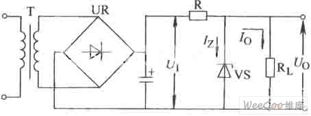
Voltage-stabilizing circuit having portable compact silicon regulator is shown as above:
(View)
View full Circuit Diagram | Comments | Reading(567)
±15V,5V three kinds of output regulated power supply circuit
Published:2011/7/20 0:41:00 Author:Fiona | Keyword: three kinds of output, regulated power supply
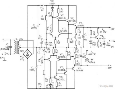
±15V,5V three kinds of output regulated power supply circuit is shown as above: (View)
View full Circuit Diagram | Comments | Reading(778)
15V,-6V double lines regulated power supply circuit
Published:2011/7/20 0:41:00 Author:Fiona | Keyword: double lines, regulated power supply
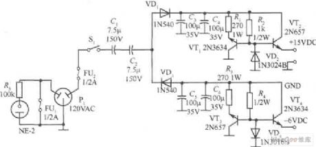
15V,-6V double lines regulated power supply circuit is shown as above:
(View)
View full Circuit Diagram | Comments | Reading(794)
The self-motivation switch regulated power supply (1)
Published:2011/7/21 1:37:00 Author:Borg | Keyword: self-motivation switch, regulated power supply
In the figure is the self-motivation switch regulated power supply circuit, which consists of the switch power tube VT2, pulse width modulator VT3, fault amplifier tube VT4, over-current protection silicon switch VT1 and pulse transformer T1, etc. And the switch tube is also the interval oscillator.
VT2, Tl, R2~R5 compose the transforming interval oscillator. After the power is on, the DC high voltage provides a proper positive bias voltage for VT2 basic electrode after the voltage is stepped down by R2~R5, so TV2 is conducting. (View)
View full Circuit Diagram | Comments | Reading(805)
The switch power supply high voltage constant current source circuit (1)
Published:2011/7/21 1:06:00 Author:Borg | Keyword: switch power supply, high voltage, constant current source
Researching instruments need a constant current source which can generate a 1MA current on the 0-3MΩ, and one is designed with UC3845 and 12V battery, the transformer is the color TV high voltage package, of which the L1 is winded for 24 turns with covered wire on the magnet core, L3 is a coil with the former high voltage package, L2 is the high voltage part of the high voltage package. L3 and LM393 compose the voltage limiting circuit, which limits the output current, by adjusting R10, the output voltage of the open circuit can be regulated. (View)
View full Circuit Diagram | Comments | Reading(598)
The constant current source of computing amplifier and Darlington transistor
Published:2011/7/21 0:56:00 Author:Borg | Keyword: computing amplifier, Darlington transistor

As the circuit is fixed with the Darlington tube BSY86, so the output current is high. The max output current value is limited by the resistor of R=150Ω, the output current is regulated by the potentiometer Rp1, and the current is irrelevant to the loading resistor RL but remains as a constant. In the figure, the potentiometer Rp1 is 10kΩ, the current can be regulated in the range of 5μA~40mA. (View)
View full Circuit Diagram | Comments | Reading(990)
The basic knowledge and drive of standard and white light LED
Published:2011/7/20 23:09:00 Author:Borg | Keyword: basic knowledge, white light LED
The simplest way to make the LED work is to connect a resistor serially with it through a voltage source. As long as the working voltage (VB) is stable, LED will shed stable light with constant power (although the power of the light will decrease as the temperature rises). By changing the resistance of the serial resistor, the light power can be adjusted to the value that is needed. For a standard LED whose diameter is 5mm, figure1 represents the function curve of forward conducting voltage(VF) and forward (IF). (View)
View full Circuit Diagram | Comments | Reading(570)
The PFC full attraction main circuit
Published:2011/7/20 22:59:00 Author:Borg | Keyword: PFC, full attraction
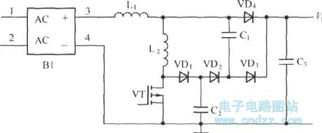
The charge process of normal charge modes is often done in homes or public places, and the charge power of normal charge modes is often 6.6KW, the typical charge time is 5~8h. The power converters of the normal charge mode and emergency charge mode are almost the same, the normal charge mode can also be adopted with the AC/DC converter. As the switch tube takes with single stage converter of the PFC function, its peak value is very high.
(View)
View full Circuit Diagram | Comments | Reading(653)
| Pages:181/291 At 20181182183184185186187188189190191192193194195196197198199200Under 20 |
Circuit Categories
power supply circuit
Amplifier Circuit
Basic Circuit
LED and Light Circuit
Sensor Circuit
Signal Processing
Electrical Equipment Circuit
Control Circuit
Remote Control Circuit
A/D-D/A Converter Circuit
Audio Circuit
Measuring and Test Circuit
Communication Circuit
Computer-Related Circuit
555 Circuit
Automotive Circuit
Repairing Circuit