
Index 189
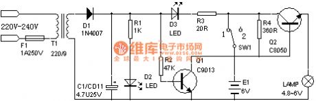
Rechargeable flashlight circuit one (4)
Published:2011/7/15 0:44:00 Author:TaoXi | Keyword: Rechargeable, flashlight
View full Circuit Diagram | Comments | Reading(1513)
LM317 Current-Expansion Circuit (2)
Published:2011/7/16 6:29:00 Author:Robert | Keyword: Current, Expansion
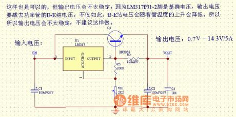
The picture shows the LM317 current-expansion circuit (2).
This circuit is also OK. But its output voltage may be unstable. Because the LM317's pin 1-2 is the reference voltage and the output voltage would minus the power transistor's B-E junction voltage. Not only this, the B-E junction voltage also would decrease while the transistor's temperature increasing. So the output voltage mey be unstable and it's not recommended to do this. (View)
View full Circuit Diagram | Comments | Reading(5016)
LM317 Current-Expansion Circuit (1)
Published:2011/7/16 7:42:00 Author:Robert | Keyword: Current, Expansion
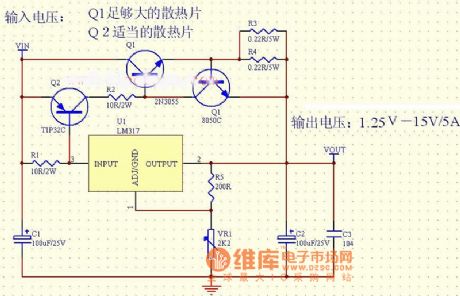
The picture shows the LM317 current-expansion circuit (1).
The input voltage is VIN.
The Q1 needs a large-enough heatsink.
The Q2 needs a adequate heatsink.
The output voltage is 1.25V-15V/5A. (View)
View full Circuit Diagram | Comments | Reading(3188)
The inverter circuit 1
Published:2011/7/16 4:17:00 Author:Christina | Keyword: inverter
View full Circuit Diagram | Comments | Reading(1289)
The inverter circuit 10
Published:2011/7/16 4:17:00 Author:Christina | Keyword: inverter
View full Circuit Diagram | Comments | Reading(3972)
[165V.HID.PWM] half bridge driver module
Published:2011/7/16 4:01:00 Author:Christina | Keyword: half bridge, driver module
![[165V.HID.PWM] half bridge driver module](/uploadfile/ic-circuit/s20117164117737.gif)
View full Circuit Diagram | Comments | Reading(3133)
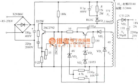
Ringing type switching power supply constant current driving circuit
Published:2011/7/15 23:18:00 Author:Christina | Keyword: Ringing type, switching, power supply, constant current, driving circuit
In the ringing type switching power supply, the power loss of the driving circuit which supplies the base current to the switching transistor is very large. The voltage UB of the transformer coil NB must ensure the minimum input voltage of the switching transistor to make the fully conduction, and the voltage UB is proportional to the input voltage Vi. When the Vi increases, the driving current Id will increases too, but the base resistance Rb increases the power loss that has the square relationship with the increasing part of Id.
When the driving current ID is increasing, the voltage stabilization diode subcircuit current will increase too, and this will cause the oscillation problem, in a certain period of time, the switch works, and in the next period of time, the switch stops working.
(View)
View full Circuit Diagram | Comments | Reading(666)
Ringing type switch power supply power expansion method
Published:2011/7/15 22:54:00 Author:Christina | Keyword: Ringing type, switch, power supply, power expansion
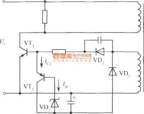
In the simple ringing current-limit power supply circuit, in order to make the output voltage stable, we need to connect the voltage-regulator diode with the base electrode of the switching transistor VTl, so the output voltage can not be adjusted. In addition, if you want to increase the output power, you need to increase the driving current. At this time, if you decrease the output current, the subcircuit current of the voltage-regulator diode will increase. This will change the voltage stabilization value of the voltage stabilization diode, even more than the allowable value of the voltage stabilization diode. So in order to improve the output power, we can use the method of add a current expansion transistor which is as shown in the figure.
(View)
View full Circuit Diagram | Comments | Reading(627)
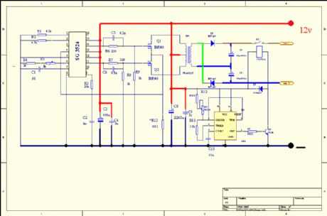
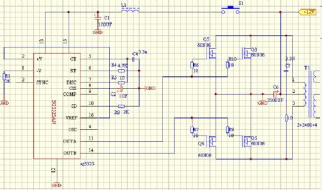
Ringing switching power supply practical circuit
Published:2011/7/15 22:44:00 Author:Christina | Keyword: Ringing, switching power supply, practical circuit
The ringing switching power supply practical circuit is as shown in the figure. The primary winding Np of the transformer is connected with the diode VD, the resistance R and capacitance C, the purpose of this connection method is to release the power of the transformer leakage inductance. That is during the conduction of the switching tube, the current accumulates the power on the leakage inductance, but this power is not transfered to the secondary stage of the transformer as the electric power. So it produces the reverse emf when the switching tube is cutting off, there is the high surge voltage to puncture the switching tube.
(View)
View full Circuit Diagram | Comments | Reading(1025)
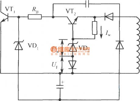
The method to change the output voltage of the ringing switch power supply
Published:2011/7/15 22:22:00 Author:Christina | Keyword: method, output voltage, ringing switch, power supply
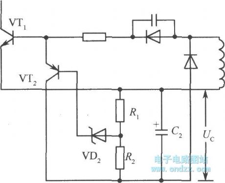
In the simple ringing current-limit type switching voltage stabilization circuit, the output voltage Vo is proportional to the negative bias Uc. If you want to change the output voltage, you need to change the Uc, as shown in the figure.
The collector electrode of the transistor VT2 is connected with the negative terminal of the capacitor C2. Once the Uc2 rises, the current which flows through the zener diode VD2 and the transistor VT2 will increase to conduct VT2. Because the collector electrode current of VT2 shortens the conduction time of the switching transistor VT1, so we can cut off the circuit in advance to reduce the output voltage Vo. (View)
View full Circuit Diagram | Comments | Reading(663)
Dual polarity voltage stabilizer with the three-port voltage stabilizer
Published:2011/7/16 5:52:00 Author:Christina | Keyword: Dual polarity, voltage stabilizer, three-port, voltage stabilizer
View full Circuit Diagram | Comments | Reading(634)
The inverter circuit 14
Published:2011/7/16 4:26:00 Author:Christina | Keyword: inverter
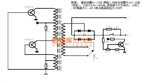
Data: base coil 8-10 turns (two groups), Primary coil 18-24 turns (two groups), Subprime coil600-800 turns, the high power relay. The 39 and 2.7ohms resistabce is 2-4W; the 6uF capacitance's voltage is 1000V.
(View)
View full Circuit Diagram | Comments | Reading(712)
The inverter circuit 13
Published:2011/7/16 4:22:00 Author:Christina | Keyword: inverter
View full Circuit Diagram | Comments | Reading(863)
The inverter circuit 12
Published:2011/7/16 4:18:00 Author:Christina | Keyword: inverter

View full Circuit Diagram | Comments | Reading(833)
The inverter circuit 11
Published:2011/7/16 4:18:00 Author:Christina | Keyword: inverter
View full Circuit Diagram | Comments | Reading(2412)
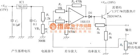
Voltage stabilization power supply circuit with the operational amplifier
Published:2011/7/16 5:56:00 Author:Christina | Keyword: Voltage stabilization, power supply, operational amplifier
View full Circuit Diagram | Comments | Reading(544)
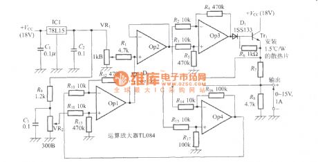
Voltage stabilizer, constant current circuit with the operational amplifier
Published:2011/7/16 5:55:00 Author:Christina | Keyword: Voltage stabilizer, constant current, operational amplifier
View full Circuit Diagram | Comments | Reading(970)
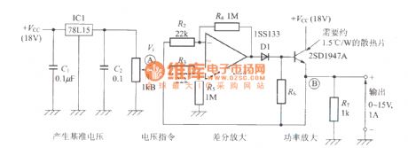
Constant current power supply circuit with the operational amplifier
Published:2011/7/16 5:54:00 Author:Christina | Keyword: Constant current, power supply, operational amplifier
View full Circuit Diagram | Comments | Reading(868)
DC voltage doubler power supply
Published:2011/7/16 5:41:00 Author:Christina | Keyword: DC, voltage doubler, power supply
DC voltage doubler power supply (View)
View full Circuit Diagram | Comments | Reading(567)
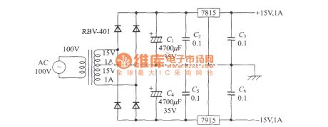
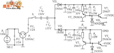
15V, -6V two-path regulated power supply circuit diagram
Published:2011/7/17 1:01:00 Author:nelly | Keyword: two-path regulated power supply
View full Circuit Diagram | Comments | Reading(668)
| Pages:189/291 At 20181182183184185186187188189190191192193194195196197198199200Under 20 |
Circuit Categories
power supply circuit
Amplifier Circuit
Basic Circuit
LED and Light Circuit
Sensor Circuit
Signal Processing
Electrical Equipment Circuit
Control Circuit
Remote Control Circuit
A/D-D/A Converter Circuit
Audio Circuit
Measuring and Test Circuit
Communication Circuit
Computer-Related Circuit
555 Circuit
Automotive Circuit
Repairing Circuit