
Index 187
0~20v,1A regulated power supply circuit
Published:2011/7/17 7:36:00 Author:Fiona | Keyword: regulated power supply
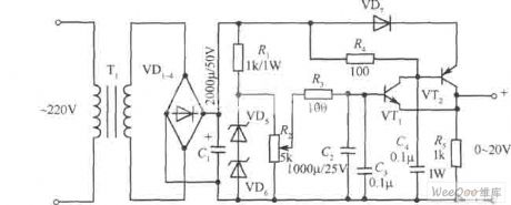
0~20v,1A regulated power supply circuit is shown as above:
(View)
View full Circuit Diagram | Comments | Reading(1458)
4W Switch-type 5V Stabilized Voltage Direct Current Power Circuit
Published:2011/7/18 6:12:00 Author:Sue | Keyword: Switch-type, Stabilized Voltage, Direct Current, Power
View full Circuit Diagram | Comments | Reading(984)
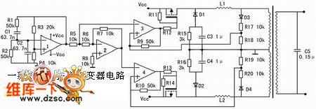
High Efficiency Sine Invertor Circuit
Published:2011/7/15 5:59:00 Author:Sue | Keyword: High Efficiency, Sine, Invertor
View full Circuit Diagram | Comments | Reading(816)
VHF 0.5 W TV Transmitter Circuit
Published:2011/7/15 21:07:00 Author:Joyce | Keyword: VHF, 0.5 W , TV, Transmitter

The TV transmitter introduced here can send audio and video signals of satellite television receivers, VCDs and video recorders in open circuit, and receives signals with open antennas. It is suitable for self-made programs of working units, schools, and factories. When folded dipole antenna is used to send signals, the covered distance is longer than 800 m.
The circuitry is as shown in figure 1.IC1 is a dedicated circuit for TV RF modulators.It will choose SAW oscillator of same frequency point to modulate audio and video signals into RF signals of TV1 ~ 12 channels. Incomplete signals and sub wave signals will be filtered out by filter network A1 before RF signals output by IC1 is coupled to RF power amplifier circuit by C15 to be amplified and sent out. (View)
View full Circuit Diagram | Comments | Reading(5273)
K6274K and K6274D-the image intermediate frequency band pass filter integrated circuit
Published:2011/7/15 19:52:00 Author:Borg | Keyword: intermediate frequency, band pass
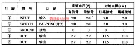
K6274K and K6274D belong to a kind of image intermediate frequency band pass filter integrated circuit, which are widely used in Konka S serial large screen color TV sets.1. Function featuresK6274K and K6274D contain the eclipse PAL/NTSC switch control circuit, band pass filter circuit and other additional function circuits.2. pin functions and dataK6274K and K6274D are in the 5-pin single in-line package, which are in Konka P2960S and P2971S large screen color TV sets, and the pin functions and data are listed in table 1-1.
table 1-1 pin functions and data of K6274K and K6274D (View)
View full Circuit Diagram | Comments | Reading(849)
IN706, 1N711 and 1N712—the karaoke mixed digital integrated circuit
Published:2011/7/15 20:07:00 Author:Borg | Keyword: karaoke, integrated circuit
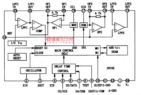
1.the internal circuit of 1N706The internal circuit of N706 is shown in figure 1-1, which contains the mixed and coupled low-pass, high-pass, A/D, D/A and clock oscillating circuit, etc. besides, there is a function of sleep for selection which can reduce the power consumption, so it’s convenient to save the power consumption of users.
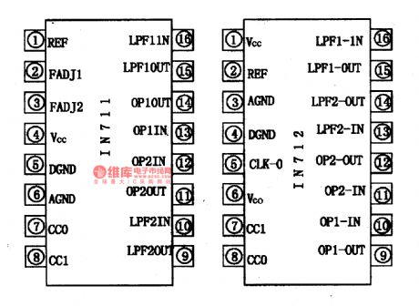
2. the main parameters of 1N706, 1N711 and IN7121N706, 1N711 and IN712 have the following main parameters. The power supply voltage is +5V, the static working current is 18MA; when RL=47K, the voltage gain is 2.5dB; when THD=10%, the max output voltage is 1V.
(View)
View full Circuit Diagram | Comments | Reading(1092)
ICE1QS01—the integrated circuit of the new switch power supply quasi-resonance controller
Published:2011/7/15 20:58:00 Author:Borg | Keyword: integrated circuit, switch power supply, quasi-resonance controller
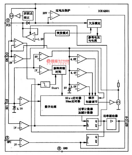
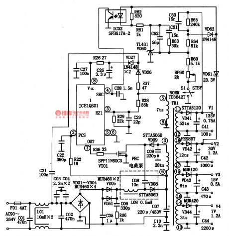
ICE1QS01 is an integrated circuit of the new switch power supply quasi-resonance controller, which is used in the TV, VCR and DVD player, satellite receiver, laptop charger and other switch power supply.1. the internal circuitICE1QS01 integrates the digit processor, standby abrupt mode and reversing point adjusting circuit, whose internal circuit is shown in Figure 1-1.
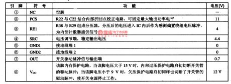
Figure 1-1 the internal circuit of ICE1QS012. pin functions and dataICE1QS01ES is in 8-pin DIP package, whose pin functions and data are listed in table 1-2.
(View)
View full Circuit Diagram | Comments | Reading(3763)
Adjustable Power Supply Circuit of IR2111
Published:2011/7/17 5:34:00 Author:Michel | Keyword: Adjustable Power Supply Circuit
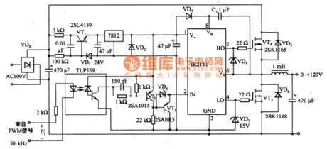
The adjustable power supply circuit of IR2111 is shown as above.In the circuit,IR2111 adopts VD3 and C1 to generate the boost voltage which is more than 12V.Thus it is not necessary to use high grade driving power supply.AC11OV turns into 140V DC voltage after VDB rectifying and it drops to 24V after flowing through VT1 and VD1.And then it provides 12V voltage for IR2111 after flowing through three ports regulator 7812. PWM output of half bridge switch power supply turns into DC voltage Ui via smooth induction and capacitance and it is added to port 2 and 3 of TLP559. (View)
View full Circuit Diagram | Comments | Reading(9113)
Automatically Charging Circuit of Battery
Published:2011/7/16 11:25:00 Author:Michel | Keyword: Battery Charging Circuit
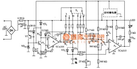
The above picture is automatically charging circuit of battery.This circuit consists of constant current circuit and automatically cut-off the circuit etc.A1 makes both ends of RL keep the same,which ensures constant charging current IZ.VDZ1 provides 18 V benchmark voltage for the base of VDZ1,It produces constant voltage drop on R2, the voltage drop is added to phase input terminal of A1.After the comparison of A1 and RL voltage drop,IZ keeps constant value.When RL is in short-circuit, resistance R3 of the output end will cut off VT3 base current and charging current IZ will be cut off sequently to protect the circuit.Functions of VD4 and VD5 are that prevent batteries discharging via VT3 when the charger cuts off. (View)
View full Circuit Diagram | Comments | Reading(1063)
Isolation Regulated Power Supply Circuit of NE555
Published:2011/7/16 21:55:00 Author:Michel | Keyword: Regulated Power Supply Circuit
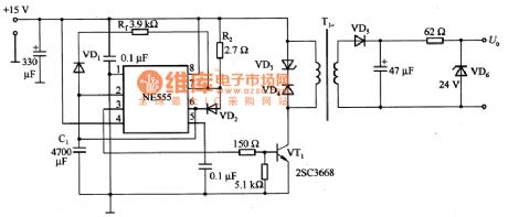
The picture is isolation regulated power supply circuit of NE555.In the circuit,R1 and R2 adjust and drive the conduction and off time of VT1.When R1 = R2,feet 3 of NE555 outputs rectangular wave with 50% dutyfactor but actually VT1 conduction is a little late, thus it needs to be adjusted lightly.VT1 conduction time is determined by R2 and C1 and the deadline depends on C1 and R1.When output voltage is high PWL,the charging time is t1 and the dischrging time is t2 when it is low PWL and t1=0.693R2C1(s),t2=0.693R1C1(s). (View)
View full Circuit Diagram | Comments | Reading(1349)
Regulated Voltage Power Supply Circuit of MC33363
Published:2011/7/17 5:23:00 Author:Michel | Keyword: Regulated Voltage, Power Supply Circuit
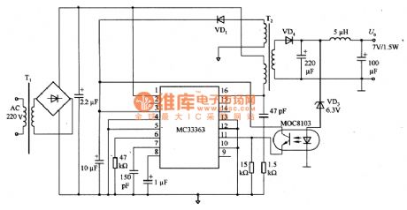
The picture 54 is regulated voltage power supply circuit of MC33363.MC33363 in the circuit is intergrated controller with gradual pulse current tester.In this application circuit,feet 10 (feedback) reaches the ground and the intergrated controller can work when it is the biggest dutyfactor(50%).When the primary level reaches the maximum limit,each output pulse is cut off.The biggest advantage of thr controller is that it can control the peak value and oscillation frequency.
(View)
View full Circuit Diagram | Comments | Reading(1412)
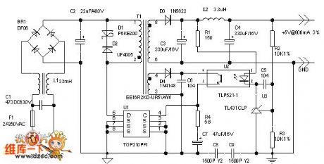
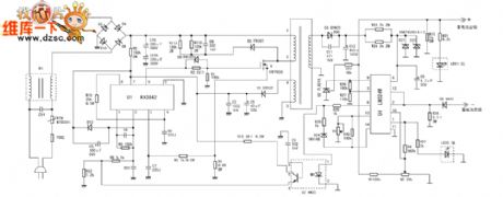
The low-power switch power supply circuit composed of UC3842
Published:2011/7/17 21:14:00 Author:Borg | Keyword: low-power switch, power supply
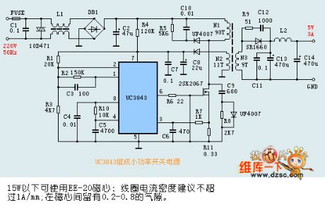
EE-20 core can be used when it is under 15W; the density of the coil current would better be under 1A/mm; the air-gap of between the cores is 0.2-.08. (View)
View full Circuit Diagram | Comments | Reading(14752)
The BUCK pre-stable circuit
Published:2011/7/17 21:06:00 Author:Borg | Keyword: pre-stable circuit
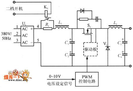
The BUCK pre-stable circuit is shown as above.
(View)
View full Circuit Diagram | Comments | Reading(683)
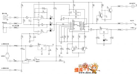
The charger principle circuit of the intelligent pulse e-bicycle
Published:2011/7/17 21:34:00 Author:Borg | Keyword: charger principle circuit, e-bicycle
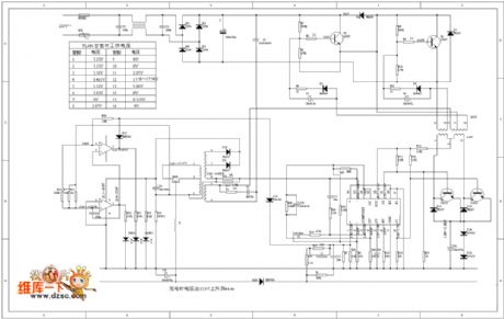
The charger principle circuit of the intelligent pulse e-bicycle is shown as above.
(View)
View full Circuit Diagram | Comments | Reading(808)
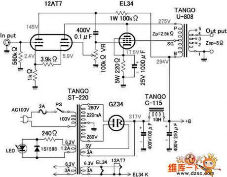
The EL34 raysonic circuit
Published:2011/7/17 21:05:00 Author:Borg | Keyword: raysonic
View full Circuit Diagram | Comments | Reading(2946)
the priciple circuit of the e-bicycle
Published:2011/7/17 21:36:00 Author:Borg | Keyword: priciple circuit, e-bicycle
View full Circuit Diagram | Comments | Reading(752)
The charger circuit of Little Antelop SMA-36C3A e-bicycle
Published:2011/7/17 21:38:00 Author:Borg | Keyword: charger circuit, e-bicycle
View full Circuit Diagram | Comments | Reading(1859)
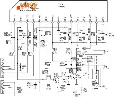
the power supply circuit of the DATAS HC-7424P color TV screen
Published:2011/7/17 21:39:00 Author:Borg | Keyword: power supply circuit, TV screen
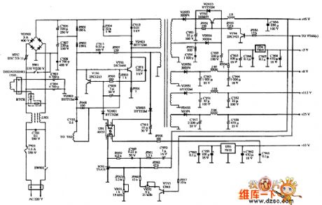
View full Circuit Diagram | Comments | Reading(2784)
the classic video amplifier circuit
Published:2011/7/17 21:41:00 Author:Borg | Keyword: video amplifier
View full Circuit Diagram | Comments | Reading(664)
48 V input 12 V output DC step-down voltage circuit
Published:2011/7/16 4:23:00 Author:Fiona | Keyword: DC step-down voltage
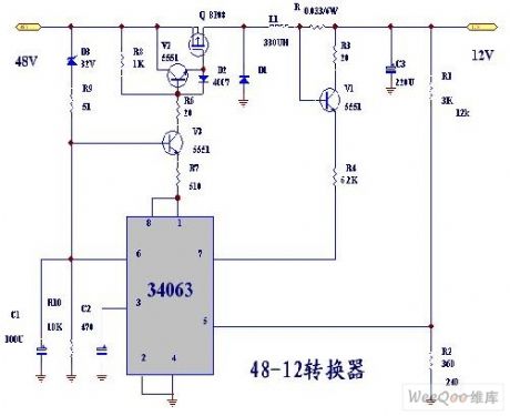
48 V input 12 V output DC step-down voltage circuit is shown as above:
(View)
View full Circuit Diagram | Comments | Reading(1952)
| Pages:187/291 At 20181182183184185186187188189190191192193194195196197198199200Under 20 |
Circuit Categories
power supply circuit
Amplifier Circuit
Basic Circuit
LED and Light Circuit
Sensor Circuit
Signal Processing
Electrical Equipment Circuit
Control Circuit
Remote Control Circuit
A/D-D/A Converter Circuit
Audio Circuit
Measuring and Test Circuit
Communication Circuit
Computer-Related Circuit
555 Circuit
Automotive Circuit
Repairing Circuit