
Index 47
THREE VOLT LOW BATTERY VOLTAGE FLASHER
Published:2012/9/5 20:51:00 Author:Ecco | Keyword: THREE VOLT , LOW BATTERY VOLTAGE, FLASHER
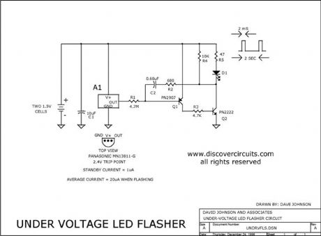
This circuit is designed to monitor two alkaline cells (3v) that form the battery often used in portable electronic equipment. It use an inexpensive IC from Panasonic that is connected to an efficient LED flashing circuit. When the battery voltage drops below a certain point the circuit flashes the LED.
Source: discovercircuits (View)
View full Circuit Diagram | Comments | Reading(2229)
0.5V Negative Supply
Published:2012/9/5 20:39:00 Author:Ecco | Keyword: 0.5V , Negative Supply
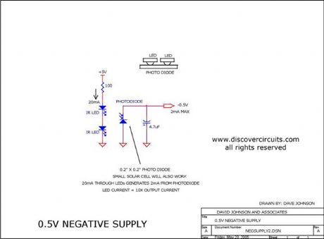
Although not very efficient, this simple circuit, consisting of two LEDs and a photo diode, generates a negative voltage with a current level of a couple milliamps. It is ideal for supplying a negative rail to low power ?rail to rail? op amp circuits, which need to have a true zero volts output.
Source: discovercircuits (View)
View full Circuit Diagram | Comments | Reading(905)
+5v Powered Charge Pump Battery Charger
Published:2012/9/4 20:44:00 Author:Ecco | Keyword: +5v, Powered Charge Pump , Battery Charger
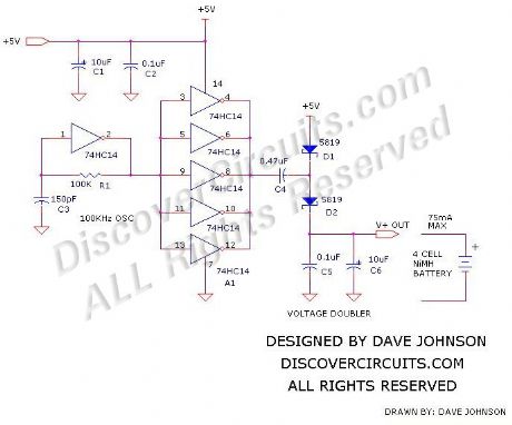
The circuit below will trickle charge a four cell pack of AA or AAA NiMH batteries. The circuit draws current from the +5v available a USB connection and pumps about 70ma of current into the battery. This should be enough current to fully charge a pack of 2500ma-hour cells in about 36 hours. The circuit uses a single 74HC14 hex Schmitt trigger inverter in conjunction with a voltage doubler charge pump circuit.
Source: discovercircuits (View)
View full Circuit Diagram | Comments | Reading(1410)
ELECTRIC FIELD DISTURBANCE MONITOR - Front End + Power Supply Circuits
Published:2012/9/4 20:11:00 Author:Ecco | Keyword: ELECTRIC, FIELD , DISTURBANCE MONITOR , - Front End + , Power Supply
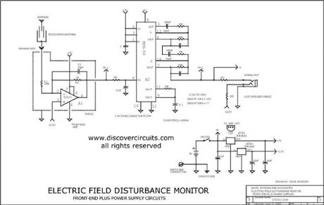
This schematic is the power supply and front-end sections of the field monitor that is discussed in more detail at Electric Field Disturbance Monitor. (this link is off-site) The system can detect human and animal motion by the electric fields they disturb.
Source: discovercircuits (View)
View full Circuit Diagram | Comments | Reading(1793)
Non-isolated Off-line AC to DC Power Supply
Published:2012/9/4 20:08:00 Author:Ecco | Keyword: Non-isolated , Off-line, AC to DC, Power Supply
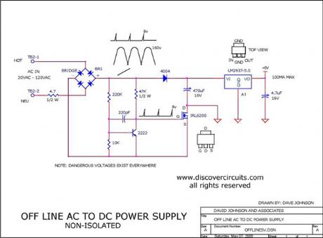
Non-isolated Off-line AC to DC Power Supply
Source: discovercircuits
(View)
View full Circuit Diagram | Comments | Reading(3003)
LOW POWER 12,000 VOLT POWER SUPPLY
Published:2012/9/4 20:08:00 Author:Ecco | Keyword: LOW POWER , 12,000 VOLT , POWER SUPPLY
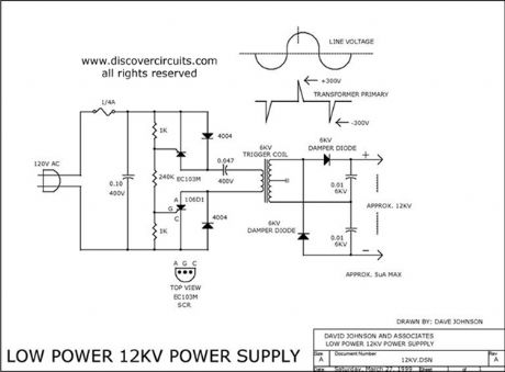
If you need about 12,000 volts DC for an ion generator this circuit might be the ticket. It draws power from the 120vac power line but it uses a small 6KV camera flash trigger coil. The output signal is isolated from the power line. Although the circuit can only deliver about 5uA of current it can produce dangerous shocks, so be careful.
Source: discovercircuits (View)
View full Circuit Diagram | Comments | Reading(2119)
Classic Plus and Minus DC Power Supply
Published:2012/9/4 4:13:00 Author:Ecco | Keyword: Classic, Plus , Minus, DC Power Supply
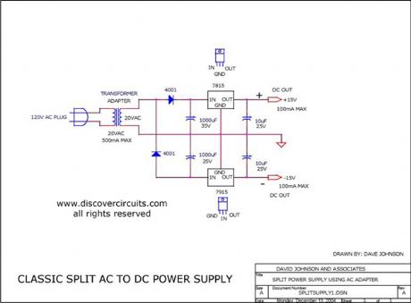
This is a classic example of a regulated DC power supply that produces both a positive 15v and a negative 15v from a 20vac wall adapter.
Source: discovercircuits (View)
View full Circuit Diagram | Comments | Reading(2498)
CAPS PROVIDE VOLTAGE BOOST TO SERIES REGULATOR
Published:2012/9/4 4:11:00 Author:Celina | Keyword: SERIES REGULATOR, VOLTAGE BOOST
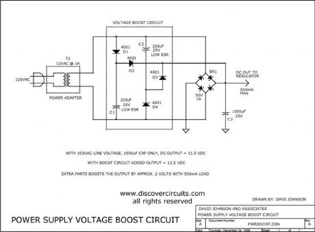
This circuit adds some capacitors and diodes to a traditional transformer type series regulator circuit to extend the normal operating range. It can insure regulation during low line voltage conditions or it can squeeze a few more watts out of a plug-in-the-wall power adapter power supply. (View)
View full Circuit Diagram | Comments | Reading(813)
VARIABLE ISOLATED AC VOLTAGE SPANS 0VAC TO 280VAC
Published:2012/9/4 4:10:00 Author:Celina | Keyword: 80VAC, VARIABLE ISOLATED
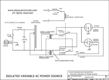
I designed and built this circuit about 25 years ago. It came in handy for many projects that were powered from 120 VAC, 240 VAC and 277 VAC. It provides complete isolation from the power line. It uses two 1:1 isolation transformers that are wired in parallel for the140vac range and in series for the 280vac range. The selector switch also diverts power to the appropriate output socket to avoid mishaps in sending the wrong voltage to the load. My home-built unit also included an AC volt and amp meter to monitor the output. However, this circuit only indicates the AC power connections. (View)
View full Circuit Diagram | Comments | Reading(895)
18v AC to DC Power Supply
Published:2012/9/4 4:02:00 Author:Celina | Keyword: 18v , AC to DC
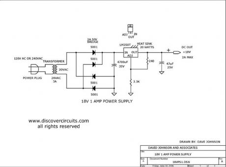
This is a classic linear power supply which produces a regulated 18v, rated at about 1 amp. (View)
View full Circuit Diagram | Comments | Reading(1251)
VARIABLE ISOLATED AC VOLTAGE SPANS 0VAC TO 280VAC
Published:2012/9/4 3:58:00 Author:Ecco | Keyword: VARIABLE , ISOLATED, AC VOLTAGE , SPANS , 0VAC TO 280VAC

I designed and built this circuit about 25 years ago. It came in handy for many projects that were powered from 120 VAC, 240 VAC and 277 VAC. It provides complete isolation from the power line. It uses two 1:1 isolation transformers that are wired in parallel for the140vac range and in series for the 280vac range. The selector switch also diverts power to the appropriate output socket to avoid mishaps in sending the wrong voltage to the load. My home-built unit also included an AC volt and amp meter to monitor the output. However, this circuit only indicates the AC power connections.
Source: discovercircuits (View)
View full Circuit Diagram | Comments | Reading(1669)
ISOLATED AC CURRENT MONITOR
Published:2012/9/4 3:31:00 Author:jailer
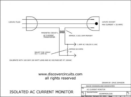
This circuit uses a small AC current transformer from Magnetek to produce an isolated voltage proportional to the AC current in the primary winding. The transformer contains a single turn primary with a low 0.001-ohm resistance. It can easily handle 30 amps of AC current and provides at least 500vac of isolation. With the components shown, the output AC voltage is scaled so 1 amp of current produces 100mv of AC voltage. (View)
View full Circuit Diagram | Comments | Reading(2)
Low Power Under- and Over-Voltage Monitor
Published:2012/9/4 1:47:00 Author:Ecco | Keyword: Low Power , Under- and Over-Voltage, Monitor
This voltage monitor has two threshold, VTH for undervoltage and VTH’ for overvoltage. Using the component values shown in the schematic diagram below, this circuit give 6V for VTH and 15V for VTH1. Above 6V, the LED indicator of this voltage monitor circuit will increase the flash rate until reach 15V. This circuit will stop flashing at voltage below 6V and above 15 volts since there will be no current flowing through C1. At threshold boundary, the output of LM10 will saturate to negative below VTH and saturate to positive above VTH’.
To customize circuit we can select the resistors values according to chosen VTH and VTH’ using the following formula:
VTH=[R4(R1+R2)Vref]/[R1(R3+R4)];
VTH’=[R4(R1+R2)Vref]/[R1(R3+R4)-R3(R1+R2)]
Since the current consumption is very small (around 500uA), this voltage monitor will be suitable for various application demanding low cost solution, such as battery monitoring, small testing equipments, or power line indication.
(source: freecircuitdiagram)
(View)
View full Circuit Diagram | Comments | Reading(2221)
5V FET Voltage Regulator
Published:2012/9/4 1:45:00 Author:Ecco | Keyword: 5V , FET , Voltage Regulator
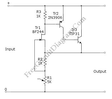
This voltage regulator circuit gives a stable 5V output from unregulated inputs (more than 5V). The stability of the output voltage is good enough, only change less than 0.1 volts when the load current changes about 60mA. Here is the schematic diagram of the circuit:
The basic principle of the voltage regulation rely on the mechanism of keeping the the FET’s gate voltage at the cut-off point. The FET’s gate volage is the voltage across R2. At zero volt (when there is no current flowing through R2), the FET will be conducting, and a small current at FET (Tr1) will cause much larger current to flow through Tr3. This current will flow through R2 and the gate voltage becomes negative. A some level the negative voltage at FET’s gate will cut-off the FETs current and keep the output voltage stable. (source: freecircuitdiagram)
(View)
View full Circuit Diagram | Comments | Reading(1838)
26V-to-5000V DC-DC Converter
Published:2012/9/4 1:44:00 Author:Ecco | Keyword: 26V-to-5000V, DC-DC Converter
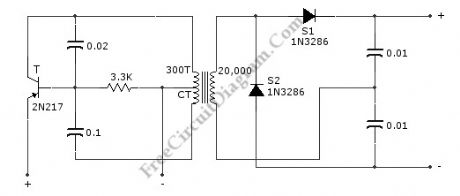
This circuit can provide 5,000 VDC from 26 VDC. This circuit has ripple of under 0.01% due to Voltage-doubling capacitors. As sinusoidal oscillator, a 2N217 transistor is used. The diode and the capacitors at the output stage should be of high voltage type. Here is the schematic diagram of the circuit:
(source: freecircuitdiagram)
(View)
View full Circuit Diagram | Comments | Reading(951)
Transceiver Saver (Overvoltage Protector)
Published:2012/9/4 1:42:00 Author:Ecco | Keyword: Transceiver Saver , Overvoltage Protector

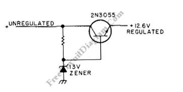

This is a transceiver saver circuit that protect a transceiver device (applicable to other device as well) from overvoltage of the power supply. This circuit is used to protect the device by regulating the power supply, avoiding damaging the device if overvoltage occurs. If the transceiver transmits current of above 2A, a heatsink should be used for the transistor. The value of resistor must provide output of 12.6 V during normal operation, you can make trial and error through measurement when choosing this., you can start with value around 100R. It’s recommended to use a high wattage Zener diode. Here is the schematic diagram of the circuit: (source: freecircuitdiagram)
(View)
View full Circuit Diagram | Comments | Reading(817)
Auto-Off 12V NiCd Battery Charger
Published:2012/9/4 1:40:00 Author:Ecco | Keyword: Auto-Off , 12V , NiCd Battery Charger
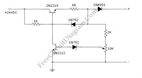
NiCd/NiCad battery charger circuit is still needed since some application demanding high current is still rely on NiCd type, since this type is still superior in term of high current output (low internal resistance) and low cost. This battery charger circuit is used to charge 12V NiCd battery at around 74 mA until battery is fully charged. This circuit need around 4 hours to fully recharge a totally empty/dead battery, depends on the battery capacity. Here is the schematic diagram of the circuit:
This circuit is basically a current source with auto cut-off. The current regulation is done by maintaining a fix voltage across a 68R at the emitter of 2N2219 transistor. This voltage is stabilized by a 5.6V zener diode 1N752, which keep the voltage at 68R resistor at around 5V, giving a constant current of 74 mA. The auto-off feature work by monitoring the output voltage (before the 1N4001 diode) relative to ground, as this voltage increases in accordance with the battery voltage which is being charged. After the battery voltage reach the fully-charged level, the lower 1N752 zener diode will pass the current to activate the 2N222 transistor, which short the upper transistor’s base, turning off the charging process. To calibrate the shut off point, connect a 270 ohm / 2 Watt resistor across the charge terminal and adjust the pot until the charging terminal voltage show 15.5V level.
(View)
View full Circuit Diagram | Comments | Reading(2988)
Foldback Current Limited High Voltage Regulator
Published:2012/9/4 1:36:00 Author:Ecco | Keyword: Foldback , Current Limited, High Voltage , Regulator
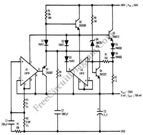
This circuit is high voltage regulator which has foldback current limiter protection. This circuit uses LM10 comparator with voltage reference, and this core integrated circuit is connected directly to high voltage circuitry. This high voltage direct connection is possible since the IC is inserted to a bias network and directly drop the applied voltage, so this IC is only suffering small voltage across its supply pins.
The foldback current limiter is different with ordinary current limiter in the way the limiter responds to dynamic load. When we plot the regular current limiter, when the load draw a linearly increasing current, the plot of the current will be linear ramp which stops at a specified level determined by the limiter. A foldback current limiter will give same response until the current reach the maximum level, but will fold the current back to a much lower current level if the load try to further increase the current. This foldback action will prevent the final driver transistor in the regulator from overheating. (source: freecircuitdiagram)
(View)
View full Circuit Diagram | Comments | Reading(1791)
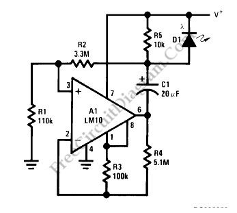
LM10 Battery Voltage Threshold Indicator
Published:2012/9/4 1:33:00 Author:Ecco | Keyword: Battery , Voltage Threshold , Indicator
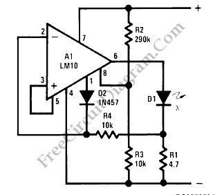
A battery threshold indicator circuit shown in the schematic diagram below has current regulation mechanism in driving the LED. A sufficient current should be satisfied at the minimum voltage but no excessive current when the voltage is at the highest level. Balance pin (5) is used as the reference voltage for regulating the current. This pin generate 23 mV, which is internally temperature compensated.
This battery voltage threshold indicator circuit overcomes the difficulties caused by voltage change across the diode biasing resistor.
When the voltage on the reference-feedback terminal (8) drops below 200 mV, the reference output (1) rises to supply the feedback voltage to the op amp through D2, so the LED current drops to zero. The minimum threshold voltage for these circuits is basically imited by the bias voltage for the LEDs. Typically, this is 1.7V for red, 2V for green and 2.5V for yellow. These two circuits can be made to operate satisfactorily for threshold voltages as low as 2V if a red diode is used. (source: freecircuitdiagram)
(View)
View full Circuit Diagram | Comments | Reading(0)
Direct High Voltage DC Regulator
Published:2012/9/4 1:31:00 Author:Ecco | Keyword: Direct, High Voltage, DC Regulator
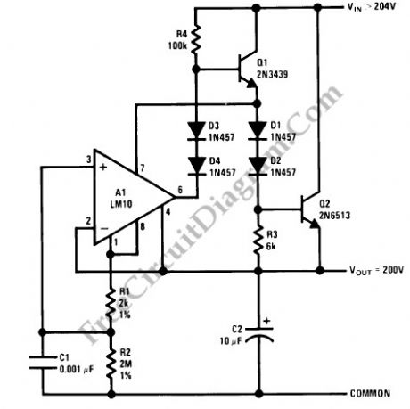
This regulator circuit stabilize the output voltage at 200V directly (without a transformer). Although the output voltage is high, this circuit only suffer a tension of the voltage drop (Vinput-Voutput), which is suffered mainly by the transistors. The op-amp suffers even less tension, since it regulate the applied voltage at their pins around the level of transistor’s bias voltage level.
(source: freecircuitdiagram)
(View)
View full Circuit Diagram | Comments | Reading(1769)
| Pages:47/291 At 204142434445464748495051525354555657585960Under 20 |
Circuit Categories
power supply circuit
Amplifier Circuit
Basic Circuit
LED and Light Circuit
Sensor Circuit
Signal Processing
Electrical Equipment Circuit
Control Circuit
Remote Control Circuit
A/D-D/A Converter Circuit
Audio Circuit
Measuring and Test Circuit
Communication Circuit
Computer-Related Circuit
555 Circuit
Automotive Circuit
Repairing Circuit