
Index 45
12 Volt Dual Power Supply circuit
Published:2012/9/25 0:46:00 Author:muriel | Keyword: 12 Volt,Dual,Power Supply
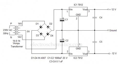
Here is the standard dual power supply using the Positive and Negative Voltage regulator ICs. It can give +12 volt and – 12 volt DC with a common ground.This power supply is ideal to power amplifier circuits that require well regulated dual power supply. It can give 1 ampere current to the circuit.14-0-14 volt 1 Ampere step down transformer is used to drop 230 volt AC to 14 volt DC which is then rectified using the standard full wave bridge rectifier comprising D1 through D4.Smoothing capacitors C1 and C2 remove the ripples from low volt AC.Two regulator ICs are used to generate + 12 volt and – 12 volt DC. IC1 is 7812 positive regulator giving +12 volt regulated output .
12 Volt Dual Power Supply Circuit
(View)
View full Circuit Diagram | Comments | Reading(3974)
Regulated Charger circuit
Published:2012/9/24 22:27:00 Author:muriel | Keyword: Regulated,Charger
Most of the battery chargers do not have current and voltage regulation provisions. The step down voltage is simply used for charging. These chargers develop internal resistance so the output voltage drops when the battery is connected to the charger. Moreover, fluctuations in the AC line also affect the charging process. This current and voltage regulated charger eliminates these drawbacks and can provide well regulated 12 volt DC for charging.
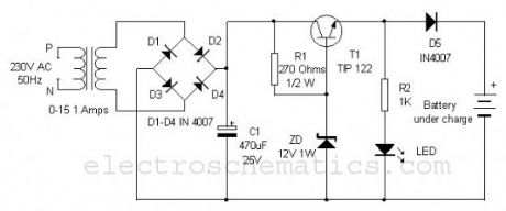
0-15 1 Ampere step down transformer drops 230 volt AC into 15 volt AC which is rectified through the bridge rectifier comprising D1 through D4. The rectified DC is then made ripple free by C1 and send to the collector of the medium power NPN transistor T1 to give regulated output. Resistor R1 and Zener diode ZD are used for both voltage and current regulation. Output current from the emitter of T1 depends on the value of R1 which can be changed according to the requirement using the ohms law. 12 volt Zener diode gives constant 12 volts to the base of T1 so that output voltage remains 12 volt irrespective of the input fluctuations. Diode D5 is polarity protector that prevents short circuiting if the polarity of the battery is reversed. LED indicates the charging process.
Regulated Charger Circuit
(View)
View full Circuit Diagram | Comments | Reading(1539)
Do It Yourself Solid State Relay
Published:2012/9/24 22:24:00 Author:muriel | Keyword: Solid State, Relay
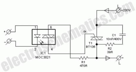
One advantage of solid-state relay (SSR) over conventional electro-magnetic relay (EMR) is its tear and wear free operation. S201S01 from Sharp is a good example. Here is the circuit diagram of a DIY SSR project, which is in fact an isolated triac power controller.The switching output from any dc circuit can be connected to pin 1 of opto-isolator (IC1) through a suitable current limiting resistor. Pin 2 of IC1 is grounded.Pin 6 of IC1 is connected to one main terinal of Triac (T1) through resistor R1 and pin 4 drives the gate terminal of T1.
To limit the rate of change of voltage, a snubber circuit (R2-C1) is added across T1.When current passes through the internal LED of IC1, internal diac is triggered and the diac provides the gate pulse to T1. Now T1 is fired to drive the ac mains operated load at its output.
After construction of the solid state relay on a common pcb, enclose the whole circuit in a very small ABS case. Now drill suitable holes to mount four labelled input and output terminals. Since switching is accomplished by triac T1, don’t touch the internal parts while AC supply is plugged in.
DIY Solid-State Relay Circuit Schematic
(View)
View full Circuit Diagram | Comments | Reading(2316)
Battery Backup Circuit
Published:2012/9/24 4:25:00 Author:muriel | Keyword: Battery Backup

This Battery backup circuit can be added to surveillance systems like alarms to power the circuit during Mains failure. The battery backup will immediately take up the load without any delay.The circuit is simple to construct. Regulator IC 7809 gives 9 volts regulated DC for powering the circuit as well as to charge the rechargeable battery. LED indicates the power on status. When the mains power is available, diode D1 forward biases and passes current into the battery through R2. Value of R2 is selected to give 90 mA current (9/100 = 0.09A) for slow charging. When the mains power fails, D1 reverse biases and D2 forward biases and backup the circuit. The same circuit can be used in circuits having 6 volt 7.5Ah battery. For 12 volt battery, use 7814 regulator IC and 14 Volt input.
Battery backup circuit diagram
(View)
View full Circuit Diagram | Comments | Reading(4434)
High Voltage Converter Circuit
Published:2012/9/24 4:14:00 Author:muriel | Keyword: High Voltage, Converter
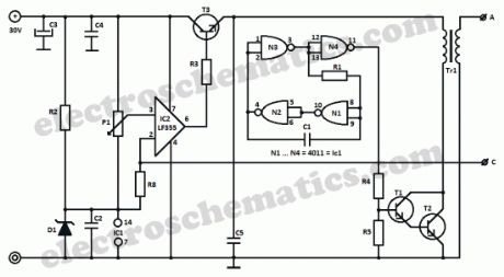
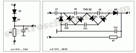
Starting from a 30 volt power supply this high voltage converter circuit can deliver a voltage between 0 to 3 kV (version 1) or from 0 to 10 kV (version 2).IC 4011 gates N1 … N3 are connected as astable multivibrator that commands the Darlington T1/T2 with an rectangular impulse of 20 kHz.The transistors cannot be brought to saturation because of the low current that goes through them which will result in a very short block period. The rapid blocking of the transistors will produse an impulse of almost 300 V in the transformer’s T1 primary winding. This voltage is multiplied by the numbers of turns from the secondary winding.
For the first version it uses a monophased rectification. The second one uses a cascade rectifier from an old TV set and it delivers a 3 times higher voltage.
3 kV/10 kV High-Voltage Converter Schematic
Version 1 and 2 of the voltage converter
IC2 LF355 regulates the output voltage by comparing the P1′s voltage with that from the common point of the voltage divider R6/R8 or R7/R8. If the output outreaches the established voltage level, IC2 will reduce the supply voltage from the output through T3.
The most important part of the high voltage converter is the transformer. You may use a variety of cores E, E+I or ferrite with 30 mm diameter. The core must not have any air gap and a value for Al of 2000 nH is pretty good. The primary winding consists of 25 turns of 0.7 … 1 mm enamelled copper and the secondary winding consists of 500 turns of 0.2 … 0.3 mm conductor. Both of the windings must have very good insulation from each other.
Regarding this high voltage converter, please remember:
capacitor C6 must support a voltage of at least 3 kV
R6 at version 1 is made of six 10 MΩ resistors in series. R7 is made of six 50 MΩ resistors in series. This is done in order to eliminate the voltage spikes.
Each circuit consumes avout 50 mA without the load and 350 mA with a 2 … 3 W load. T2 and T3 transistors need good heatsinks.
Components list of the high voltage converterR1 = 4.7KR2 = R5 = 1KR3 = 330R4 = 2.7KR6 = 60MR7 = 300MP1 = 500K
C1 = 10nC2 = C4 = C5 = 100nC3 = 1000µFC6 = 10n / 3kVC7 …. C12 = from tv module TVK 32
D1 = Zener 11VD2 = D3 = BY127D4 …. D9 = from tv module TVK 32
T1 = 2N3055T2 = BF259T3 = BU208
Tr1 = read the article
IC1 = 4011IC2 = LF355?
3 Responses to “High Voltage Converter Circuit”
(View)
View full Circuit Diagram | Comments | Reading(1696)
12V Battery charger circuit
Published:2012/9/24 4:13:00 Author:muriel | Keyword: 12V, Battery charger
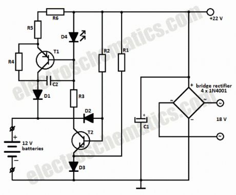
This battery charger circuit can be used to charge one or more batteries with the total nominal voltage of 12 V, meaning ten NiCd battery or six 2 V lead acid. The circuit is pretty small and can be built in a housing network adapter. The incorect usage is impossible: connecting the batteries with reverse polarity, shortcircuit of the output terminals or power loss have no impact on the charger or battery.We can use a transformer with 18 V on the secondary and then using a diode bridge to rectify the 18V ac voltage we get 22V dc on C1.
The completely discharged batteries are charged at the begining with a 6 mA current thru R2-D2 and R4-R6-D1. One the bat. have reached 0.3 – 0.5 V, the base-emitter voltage of T1 is high enough to bring the transistor in conduction.
Green LED D4 is used as an charging indicator and opens T1.There is a 60 mA current flowing thru R5-R6, this means that the charging of a 500 mAh NiCd battery will take 12 hours.
If the battery is connected with reversed polarity or there is a shortcircuit, the power transistor T1 remains blocked and the charging current can not exceed 6 – 12 mA. The current draw at maximum load is around 80 mA.
Battery charger circuit schematic
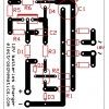
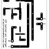
Battery charger PCB Layout
Components ListR1 = R2 = 10KR3 = 1KR4 = 5.6KR5 = R6 = 12Ω
C1 = 1nFC2 = 220µF / 35V
D1 = 1N4001D2 = D3 = 1N4148D4 = green LED
T1 = BD140T2 = BC546?
12 Responses to “12V Battery charger circuit”
(View)
View full Circuit Diagram | Comments | Reading(3050)
Solar Battery Charger Circuits
Published:2012/9/24 4:05:00 Author:muriel | Keyword: Solar, Battery Charger
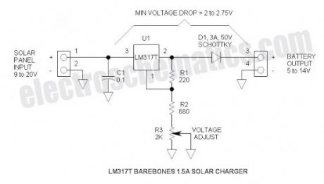
This is the most simple and affordable solar battery charger that the hobbyist can make. It has a few drawbacks over other similar controls, but offers numerous advantages. It is intended for charging lead-acid batteries, but may also be used for charging any battery at a constant voltage. Voltage output is adjustable.Advantages & Disadvantages of this solar charger
+ Simple, small & inexpensive
+ Uses commonly available components
+ Adjustable voltage
+ ZERO battery discharge when sun is not shining
– High drop-out voltage—may be marginal for 6V application
– Current limited to 1.5A
– No LED indicators—no bells or whistles
Solar battery charger specifications
Solar panel rating: 20W (12V) or 10W (6V)
Output voltage range: 5 to 14V (adjustable) (may be reduced further by shorting R2)
Max power dissipation: 10W (includes power dissipation of D1)
Typical dropout voltage: 2 to 2.75V (depending upon load current)
Maximum current: 1.5A (internally limits at about 2.2A)
Voltage regulation: ±100mV (due to regulation of series rectifier)
Battery discharge: 0mA (this control will not discharge the battery when the sun doesn’t shine)
Solar battery charger schematic
6V Applicaton
Output Voltage: Set for 7V
Input voltage:
Battery discharged (6V): 8.75V Min @ 1.5A (this is a little high for panels that are characterized for 6V applications)
Battery charged (7V): 9V Min @ 10mA (e.g.)
12V Application
Output Voltage: Set for 14V
Input voltage:
Battery discharged (12V): 14.75V Min @ 1.5A (Available from solar panel characterized for 12V operation)
Battery charged: (14V): 16V Min
Minimum Head Voltage
This is also referred to “drop-out voltage.” The input voltage must exceed the output voltage by about 2.75V @ 1.5A. Fortunately, when the battery discharged, the output voltage is lower so the solar panel voltage will also be lower.
When fully charged, the battery voltage will be high, but the current is very low—at this point, the drop-out voltage reduces to about 2V and the open circuit solar panel voltage also comes into play. The schottky rectifier was selected to reduce this head voltage requirement—the voltage drop of the schottky is about 0.5V @ 1.5A or about half that of a typical silicon rectifier.
More advanced controls have a much lower head voltage requirement and will function better under marginal conditions.
Maximum Power Dissipation
The power is limited by the thermal resistances of both the LM317T and the heat sink. To keep the junction temperature below the 125°C Max, the power must be limited to about 10W. If a smaller or less effective heat sink is used, the maximum power dissipation must be de-rated. Fortunately, the LM317 has internal temperature limiting so that if it gets too hot, it shuts down thus protecting itself from damage. Max power comes into effect when charging a 12V battery @ 1.5A: e.g. battery voltage = 12V, solar panel = 18V. P = (18V – 12V) * 1.5A = 9W. So thermally, it is carefully matched to the current rating.
If a solar panel that is characterized for 12V is applied with a 6V battery, the maximum current must be reduced to about 0.7A: e.g. battery voltage = 6V, solar panel voltage = 18V. P = (18V – 6V) * 0.7A = 9.6W. In this case, (View)
View full Circuit Diagram | Comments | Reading(3693)
Battery Status Indicator circuit
Published:2012/9/21 3:25:00 Author:Ecco | Keyword: Battery Status, Indicator
If an LED indicator is present in battery powered gadgets such as Emergency lamps, it will consume power even if the gadget is not using. This will reduce the battery voltage since the LED takes around 2 volts. So it is necessary to charge the battery continuously to keep the battery voltage level. This circuit eliminates this and the LEDs turn on only in two conditions. That is in the over charged and over discharged conditions only.
The circuit is basically a voltage controlled switch using Zener diodes. Two state LED indication is provided using a Bicolour LED. Zener diode ZD1 and the PNP transistor T1 forms the over discharge indicator switch. When the battery voltage is above the breakdown point of ZD1 (around 5 volts), it conducts and keeps T1 out of conduction. So the Red half of the bicolur LED remains off. When the battery voltage reduces below 5 volts, Zener turns off allowing T1 to conduct and Red LED turns on. This indicates that the battery is going to the over discharged state.
Zener diode ZD2 and NPN transistor T2 forms the Over charge indicator switch. When the battery voltage is below 6.8 volts (maximum voltage level), ZD cease to conduct and T2 remains off. So that the Green half of the LED also remains off. When the battery voltage increases above 7 volts due to overcharging, ZD2 conducts followed by T2 and Green LED turns on. This is the over charged state. In short, if the battery voltage is between 5 and 7 volts, both LEDs remain off. This reduces the chance of power consumption.
Battery Status Indicator Circuit
Setting
A variable power supply is necessary for the calibration. Provide 5 volts and adjust VR1 till Red LED turns on. At this point, Green LED remains off. Increase the voltage to 7volts and adjust VR2 till Green LED turns on. At this point, Red LED should remain off. Reduce the voltage to 6 volts. Both LEDs should be in the off state.?
21 Responses to “Battery Status Indicator circuit”
source: electroschematics.com
(View)
View full Circuit Diagram | Comments | Reading(2167)
Battery over discharge Indicator
Published:2012/9/21 3:25:00 Author:Ecco | Keyword: Battery , over discharge , Indicator
Most of the battery voltage indicators always remain on even if the load is off. The LED indicator and the circuit consume current which reduces the battery charge and the charger should be continuously switched on to keep the charge of the battery. Here is an ideal solution to prevent this. The indicator turns on only if the load is running. It gives a Red LED indication when the battery voltage reduces below 4.7 volts. So that the load can be switched off to prevent deep discharge of the battery.
The circuit uses the OpAmp CA3140 as a voltage comparator and SCR 2P4M as switch. The inverting input of IC1 gets half supply voltage(3V) from the potential divider R2-R3 and its non inverting input gets a higher voltage through R1. Capacitor C1 maintains stable voltage level at the non inverting input of IC1.Power supply to the IC is obtained through the SCR 2P4M when the load switches on.
Output voltage of IC1 is used to drive the deep discharge indicator LED.As long as the output voltage from IC1 is above 5 volts, Zener conducts and keep the PNP transistor off. So that LED remains off. When the battery voltage reduces below 5 volts, output voltage of IC1 also reduces to 5 volts or less. This makes the Zener out of conduction and T1 turns on and LED lights to indicate low battery level.
Battery over discharge indicator circuit
Setting
Normally IC1 will be off since SCR is not conducting. The gate of SCR (point A) should be connected after the load switch so that SCR fires only when the load turns on. Before connecting the circuit to the battery, adjust the breakdown point of Zener using a variable power supply. Give 5 volts and slowly adjust VR till LED turns on. This is the breakdown point of Zener. It will be around 5 volts. If Zener is still conducting, reduce its value to 4.1 volts. CA3140 is a low power BiMOS Op Amp and its output will be nearly full supply voltage. Once the SCR triggers, it latches itself and remains conducting even if the gate voltage is removed. SCR can be switched off by removing power through S1.?
3 Responses to “Battery over discharge Indicator”
source: electroschematics.com (View)
View full Circuit Diagram | Comments | Reading(1881)
Power Supply Regulation
Published:2012/9/20 20:54:00 Author:Ecco | Keyword: Power Supply , Regulation
Regulated power supply is necessary in some electronic circuits especially in Amplifier circuits. Poorly regulated power may cause buzzing and unwanted noise in RF and amplifier circuits. There are two methods to get regulated power supply. The most common and simple one is Zener regulated power supply. A Regulator IC of 78 XX series or Variable regulator LM317 can also be used but it may increase the cost and size of the power supply circuit. Here explains the theory behind Zener regulation. Zener Regulation is used to hold the output voltage steady, irrespective of the changes in input voltage. Zener is a sophisticated semiconductor diode. It conducts only when its breakdown voltage reaches. Zener value represents the voltage it gives. But to get easy breakdown of Zener, the input voltage must be 1-2 volts higher than that of the Zener voltage.
Low current Zener Regulation
Fig.1 shows the voltage regulation using a Zener diode.10 V input is given to a 5.6V Zener. Zener requires a minimum 5 mA current to maintain its action. This current is maintained by the series resistor R connected in series with the Zener. The value of R is important to allow at least 5 mA current for the Zener even if the load draws more current.
Zener Regulation Circuits
In the Fig.1 Imax is the current through the load. It should be maximum 250mA.
Iz is the current passing through the Zener to maintain its action
I max + Iz is the current passing through the resistor R.
Vz is the voltage across the Zener
Using these parameters, the value of the resistor R is determined using the formula
R = (Vin-Vz) / (Imax+Iz)
That is (10-5.6) / (0.25A+0.005A) = 4.40 / 0.26 = 16 Ohms. The nearest value is 18 Ohms.
Power rating of the Zener should be enough to withstand current through the Zener in no load condition.
Power rating of the Zener is calculated using the formula
P = (I max + Iz) x Vz = P = (0.25 A+0.005A) X 5.6 = 1.4 Watts. Select a Zener with more than 1.5 W rating, if the load current is 250 mA.
Rating of the resistor R is also important to handle the load current as well as the Zener current.
Current through R is I max + I z and voltage through R is Vin – Vz
So Power dissipation in R is
P= (Imax+Iz) x (Vin-Vz) = (0.25+0.005) x 10-5.6) = 1.14 W. So a 2 watt resistor is required as R if the load current is 250 mA or 0.25 A.
High Current Regulation
The circuit shown in Fig.1can be used only if the load current is less than 250 mA. If the load requires more current, say as in battery charges, transistor based Zener regulation is necessary. Fig.2 shows how a series transistor is used in combination with a Zener to give a High current voltage regulated circuit. T1 is connected as an Emitter follower. It should be either a medium power transistor like BD 139 or TIP 122 if current is less than 1A or power transistor like 2N 3055 if current is very high. Zener voltage Vz is 0.7 V (biasing voltage of T1) more than the required output. R s
Source: electroschematics.com (View)
View full Circuit Diagram | Comments | Reading(1242)
Tricky Charger circuit
Published:2012/9/20 20:53:00 Author:Ecco | Keyword: Tricky Charger
Here is a crude but efficient tricky charger for Lead Acid Battery. It uses a 12 volt car bulb as current regulator and charge status indicator. The brightness of the bulb indicates how much charge is flowing into the battery. When the battery becomes fully charged, lamp turns off. If the lamp is staying on with full brightness for more than 30 minutes, it indicates that the battery is dead and is not accepting charge.Charging current is obtained from a 15-0-15 volt secondary 2 Ampere step down transformer. Diodes D1 and D2 are rectifiers which can handle 3 ampere current. In order to give “Dirty DC” for charging, a low value filtering capacitor C1 is used. So that the DC voltage will have some ripples which is necessary for better charging of lead acid battery.
Tricky Charger Circuit diagram
The trick of the lamp is interesting. A 12 volt car tail lamp bulb is used in the circuit. It is connected in series with the positive output rail so that current flows through the bulb into the positive terminal of the battery. From the positive terminal, current passes through the battery chemistry into the negative terminal and then returns into the transformer. So the current flowing through the bulb depends on how much charge is using by the battery. When the charger is connected to the battery, the lamp turns on only if the battery requires charging current. OFF state of the bulb indicates that the battery is dead. If the battery holds some charge, bulb will turns on. If the battery is partially discharged and holding 50% charge, bulb will light brightly when the charger turns on. Then the brightness gradually reduces and finally the filament appears as a red hot line. This indicates that the battery is fully charged. The bulb also restricts the flow of current like a resistor.?
7 Responses to “Tricky Charger circuit”
Source: electroschematics.com (View)
View full Circuit Diagram | Comments | Reading(1901)
Emergency Lamp Battery Protector
Published:2012/9/20 20:51:00 Author:Ecco | Keyword: Emergency Lamp, Battery Protector
Emergency lamps do not have a facility to prevent the deep discharge of battery if the lamp remains on during day time. The fluorescent lamp filament also damages if it is glowing in low battery voltage. This causes blackening of the filament side that indicates the damaged filament. So we have to switch off the lamp in the morning and switch it on again in the evening. By adding this circuit in the emergency lamp you can reduce the job of daily switching. This circuit offers two advantages1. It prevents unnecessary discharge of battery during daytime2. It charges the battery only during night. This saves energy and prevents overcharging of the battery.The circuit is a Light controlled switch that connects the Emergency lamp circuit board with the power supply only during night through a relay. To keep the relay off during daytime, an LDR and a Schmitt trigger circuit are used. Light Dependent Resistor offers very high resistance around 10 Meg ohms in dark but in light it has only 100 ohms or less resistance. So it is an ideal component to switch on circuits based on the presence or absence of sun light. Here it is used to trigger the timer IC 555 which is designed as a Schmitt trigger.
Schmitt Trigger
The popular Timer IC 555 has two internal comparators. These are Threshold comparator and Trigger comparator. The Set and Reset action of these comparators can be used for On/ Off actions. Here the IC 555 functions as a Bistable with Schmitt trigger action. The upper comparator (Threshold comparator) of IC 555 trips at 2/3 of the supply voltage and the lower comparator (Trigger comparator) trips at 1/3 of the supply voltage. In the circuit, the inputs (pin6 and pin2) of both the comparators are shorted and connected to the junction of LDR and the Preset VR.
Emergency Lamp Battery Protector Circuit
In day light, LDR passes more current and the current into the upper comparator (pin6) is above 2/3 Vcc. This resets the internal Flip-Flop of IC. At the same time, the current into the lower comparator (pin2) is more than 1/3 Vcc. Both these condition causes low output from IC1. This low output keeps T1 off and the relay also remains off. Battery power supply to the emergency lamp circuit is connected through the Common and NO (Normally Open) contacts of the relay. So during daytime the emergency lamp circuits do not get power. The charging process is also prevented since the connection between the emergency lamp circuit and the battery is broken.
During night, LDR cease to conduct and the Schmitt trigger changes its state and output of IC1 becomes high. This triggers T1 as indicated by the LED. Relay then energizes and the NO contact makes connection with the Common contact of the relay. This connects the battery with the emergency lamp circuit.
Assemble the circuit on a Perf board and fix it inside the emergency lamp. Power to the circuit is obtained from the emergency lamp battery. Cut the positive supply wire of the emergency lamp circuit that goes to the battery. Solder the cut ends to the common and NO contacts of the relay. Adjust VR till Relay energize at a particular light level in the evening. Keep LDR on the back side of the lamp to prevent light falling on it.
Source: electroschematics.com (View)
View full Circuit Diagram | Comments | Reading(1017)
12 V Gelled-Electrolyte Battery Charger
Published:2012/9/19 21:39:00 Author:Ecco | Keyword: 12 V, Gelled-Electrolyte, Battery Charger

This circuit is a high-performance charger for gelled-electrolyte lead-acid batteries. This charger quickly recharges the battery and shuts off at full charge. It uses the well-known LM301A and LM350 ICs.Initially, charging current is limited to 2A. As the battery voltage rises, current to the battery decreases, and the current had decreased to 150 mA, the charge switches to a lower float voltage which prevents overcharge.When the start switch is pushed, the output of the charger goes to 14.5V. As the battery approaches full charge, the charging current decreases and the output voltage is reduced to 14.5V to about 12.5V, terminating the charging. Transistor then lights the LED as a visual indicator of full charge.
12V battery charger circuit schematic
?
One Response to “12 V Gelled-Electrolyte Battery Charger”
Source: electroschematic.com
(View)
View full Circuit Diagram | Comments | Reading(2669)
Wind powered battery charger
Published:2012/9/19 21:38:00 Author:Ecco | Keyword: Wind , powered, battery charger
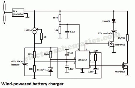
In this wind powered battery charger circuit the dc motor is used as a generator. The voltage output is proportional to its rpm. The LTC1042 monitors the voltage output and provides the following control function.1. if the voltage output is below 13.8V, the control circuit is active and the NiCad battery is charging through the LM334 current source. The lead-acid battery is not being charged.2. if the voltage output is between 13.8V and 15.1V, the 12V lead-acid battery is being charged at about 1-amp/hour rate (limited by the power FET).3. if generator voltage exceeds 15.1V (a condition caused by excessive wind speed or when the 12V battery is fully charged), the a fixed load is connected, which limits the generator rpm to prevent damage.This wind powered charger can be used as a remote source of power where wind energy is plentiful, such as on sailboats or at remote radio repeater sites. Unlike solar-powered panels, this system will function in bad weather and at night.
Battery Charger Schematic using wind energy
7 Responses to “Wind powered battery charger”
Source: electroschematic.com
(View)
View full Circuit Diagram | Comments | Reading(0)
NiMH Battery Charger circuit
Published:2012/9/19 21:37:00 Author:Ecco | Keyword: NiMH, Battery Charger
Here is a simple battery charger for the Nickel Metal Hydride battery that requires current regulated charging. The charger provides 140 mA current for quick charging of the battery.
Power supply section consists of a 0-18 volt AC 1 Ampere step-down transformer, a full wave bridge rectifier comprising D1 through D4 and the smoothing capacitor C1. Current regulation is achieved by the action of R1,R2 and the Epitaxial Darlington PNP transistor TIP 127. Resistor R1 keeps the charging current to 140 milli amperes. LED and resistor R2 plays an important role to control the base current of T1 and thus its output.
NiMH Battery Charger Circuit
Around 2.6 volts drop develops across the LED which appears at the base of T1. Emitter – base junction of T1 drops around 1.2 volts. So 2.6 – 1.2 volts gives 1.40 volts. So the current passing through R1 will be 1.40 V / 10 = 0.14 Amps or 140 Milli Amps. The LED act as the charging status indicator. LED lights only if the battery is connected to the output of circuit and the input voltage is normal.
2 Responses to “NiMH Battery Charger circuit”
Source: electroschematic.com
(View)
View full Circuit Diagram | Comments | Reading(2362)
Portable Solar Power Inverter
Published:2012/9/19 21:26:00 Author:Ecco | Keyword: Portable, Solar, Power Inverter
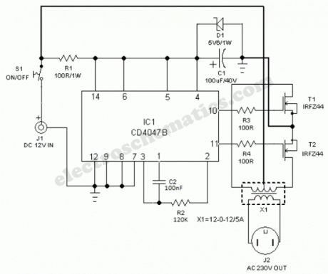
A compact and portable 12V Solar power inverter circuit that will keep away darkness. This tried and tested design converts 12V DC from the storage battery of any solar power system to 230V AC that is enough to power a number of energy saving CFLs. Just feed 12V DC input through input jack J1 (with right polarity) and flip switch S1 to ON position!The 12V power inverter circuit, optimised for CFL loads, uses IC CD4047B (IC1) as a freerunning astable oscillator. Capacitor C2 and resistor R2 are timing components. The pulse repetition rate of IC1 is determined by the value of 4.4xC2xR2. IC1 generates cmplementary squarewave signals at its output pins 10 and 11. Power Mosfets T1 and T2 serve as drivers for the high-voltage generator,realised using step-up transformer (X1).Note that an ordinary (AC 230V to 12-0-12/5Amp) step-down transformer is here used for reverse function (step-up) and its output is available at AC mains outlet J2. You can light up two to four low wattage (ie 11W at AC 230V) ready-made Compact Flourescent Lamps (CFLs) using this circuit. Two small, independent heatsinks are necessary for T1 and T2. Finally, you can try an AC 230V to 9-0-9/5Amp rated transformer as X1.
12V Power Inverter Circuit Schematic
?
34 Responses to “Portable Solar Power Inverter”
Source: electroschematic.com
(View)
View full Circuit Diagram | Comments | Reading(2023)
Battery Level Monitor circuit
Published:2012/9/19 21:15:00 Author:Ecco | Keyword: Battery Level, Monitor
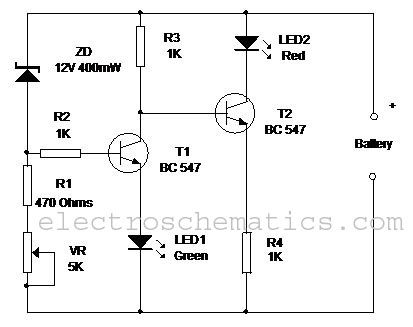
This simple circuit can monitor the charging process in 12 Volt Lead Acid battery or Tubular battery. The status of LED indicates whether the battery is accepting charge or not. It also indicates the full charge condition.The circuit can be incorporated in any battery charger like 6 volt, 9 volt, 12 volt etc. The only change needed is replacement of the Zener ZD with appropriate value. That is for 6 volt charger , use 6.1 volt Zener and for 9 volt charger it should be 9.1 volt Zener.
Battery Level Monitor Circuit
The circuit is based on the switching of two NPN transistors (BC547) to drive the corresponding LED. Zener diode ZD is connected to the base of T1 so as to switch on T1 when the Zener conducts. This happens only when the battery voltage is above 12 volts. Green LED lights when the battery voltage is normal or battery attains full charge. Resistor R1 and Preset VR adjust the base bias of T1 for smooth switching. When T1 conducts, base of T2 will be pulled to ground and T2 turns off and Red LED extinguishes.
When the circuit is connected to the battery before charging the LED indications will be
1. If the battery voltage is above 12 volts (that is the normal terminal voltage of 13.8), Zener conducts and Green LED lights and Red LED remains off.2. If the battery voltage is below 12 volts, Zener remains non conducting and Green LED remains off and Red LED lights.3. When the battery is connected to the charger, and if the battery is accepting charge, Green LED goes off and Red LED remains on. When the battery attains full charge, Green LED lights and Red LED goes off.4. If the battery is not accepting charge, Green LED never lights, even after the prolonged charging. This indicates that the battery is not attaining the normal terminal voltage above 12 volts.
5 Responses to “Battery Level Monitor circuit”
(View)
View full Circuit Diagram | Comments | Reading(2273)
Cell Phone charger using 1.5V battery
Published:2012/9/18 21:32:00 Author:Ecco | Keyword: Cell Phone charger, 1.5V battery
This article was received from Subham Chatterjee. Thank you!
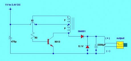
For the cell phone to charge, charger output must be above 4V and can deliver a maximum current of 500mA. This charger circuit will step up the voltage from 1.5V to 5V DC to reach the cell phone charging requirement. The circuit uses only an AA or AAA 1.5v battery (1V to 2.4V). The charger is composed of simple oscillator, a rectifier, and voltage regulator.The feedback winding F is composed 5 turns of #30 AWG magnetic wire and main winding P is composed of 6 turns of #24 AWG wire. The 5.1V zener diode and 2200uF capacitor regulates the output voltage to ensure proper charging.
The windings are not critical, you can experiment using different number of turns. If ever the charger doesn’t have any output, try to reverse the winding connection.
Cellphone charger circuit schematic
My opinion is that this can charge the cellphone battery only for short period of time because the 1.5 volt battery power capacity is much lower than the phone’s battery.
17 Responses to “Cell Phone charger using 1.5V battery”
(View)
View full Circuit Diagram | Comments | Reading(2377)
12V SCR Battery Charger
Published:2012/9/18 21:25:00 Author:Ecco | Keyword: 12V , SCR Battery Charger
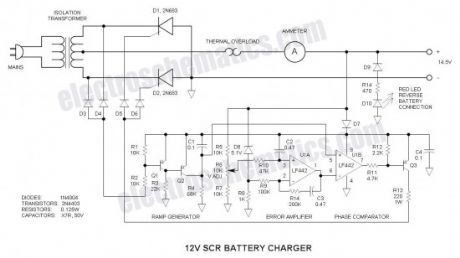
This battery charger circuit differs from the norm in a number of ways, all of which make it difficult to understand. For this reason, I do not recommend it for the beginner.Repairing /revamping a dead chargerWhat I started with was an inoperative 12amp battery charger. In hope of repairing it, I traced out the circuit, but did not like what I found—poor circuit design. So what I had to start with was an enclosure, ammeter, thermal overload interrupter, and center-tapped transformer all designed for battery charger application.
Since the maximum current delivered by the unit is a function of the transformer internal impedance, I recommend that the readers use the same type of transformer. If you are a good pack-rat (like me), you may already have a dead charger—or you can be on the lookout for one.
12V Battery Charger Schematic
SCR (Thyristor) RectifiersFirst of all, the two SCRs (silicon controlled rectifiers or thyristors) are connected with their anodes (stud or tab) grounded—this makes for excellent thermal transfer because no insulating hardware is required (if it is permissible to connect the negative terminal of the charger directly to the steel enclosure). If you do not wish to ground this point, use insulating hardware to electrically isolate the SCRs. This makes the transformer center-tap the positive terminal. The reason for this circuit placement is the ease of driving the SCR gates via the positive battery voltage—it is very unconventional as I have never seen this trick done before.
SCRs are the ideal power device choice for a battery charger because they can both regulate battery charging voltage and prevent fault current when the battery is inadvertently connected reverse. I have actually connected mine reverse and thought that the charger was inoperative until I realized what I had done.
Power Device SelectionI used two 2N690 stud-mount SCRs that I had available. Any in the series will work (2N683 through 2N690)—only the voltage rating differs and anything greater than 100V is good for the application. Other more inexpensive TO-220 candidates are: STMicroelectronics TYN616, Teccor/Littlefuse S6015L (isolated package), NXP 151-500C, or ON Seimconductor 2N6403G. Avoid sensitive gate devices.
Circuit CommonNormally circuits use a negative common—that is just the way the world seems to work, but in this case, it was more convenient to make the positive rail the common point and all visualization must be made with this in mind. The only exception is D7 that was installed to prevent damage should the battery get connected reverse. For visualization, simply short out D7. The conventional ground symbol is used for the negative rail. This tends to tie your brain in knots…
Voltage ReferenceA good battery charger tapers off when the battery voltage is above about 14V. For this to function, D6 is a 5.1V shunt zener regulator that puts out -5.1V relative to the positive rail. It is biased via R8.
Ramp GeneratorC1 and R4 form a ramp generator that generates a negative going sawtooth voltage (relative to the positive rail). It is reset to the positive rail via Q1 and Q2 at line voltage zero crossing. At zero crossing, there is no voltage at the anodes of D3 & D4 (relative to the positive rail), Q1 is off, Q2 is on and C1 is shorted. At all other points in the AC line cycle, C1 is charging. My line frequency is 60HZ. For 50HZ, increase the value of R4 to 82K.
Error AmplifierU1A
Source: electroschematics.com (View)
View full Circuit Diagram | Comments | Reading(3245)
12V Battery checker circuit
Published:2012/9/18 21:23:00 Author:Ecco | Keyword: 12V, Battery checker
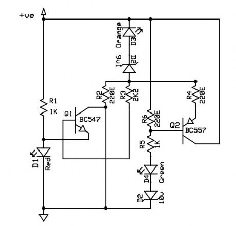
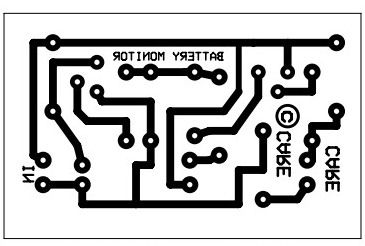
This is a 12V battery checker circuit that uses 3 LEDs that light up at their respective voltages. The red LED lights up when the battery voltage is between 8 to 10V, the orange one at voltages between 10.5V to 12V and the green one when the battery voltage is above 12.5V.This is a tried and tested battery checker circuit using one NPN and one PNP transistor. A PCB is given along with the schematic.
6 Responses to “12V Battery checker circuit”
(View)
View full Circuit Diagram | Comments | Reading(2753)
| Pages:45/291 At 204142434445464748495051525354555657585960Under 20 |
Circuit Categories
power supply circuit
Amplifier Circuit
Basic Circuit
LED and Light Circuit
Sensor Circuit
Signal Processing
Electrical Equipment Circuit
Control Circuit
Remote Control Circuit
A/D-D/A Converter Circuit
Audio Circuit
Measuring and Test Circuit
Communication Circuit
Computer-Related Circuit
555 Circuit
Automotive Circuit
Repairing Circuit