
Index 56
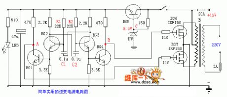
Simple and practical inverter circuit diagram
Published:2011/9/9 2:24:00 Author:Ecco | Keyword: Simple, practical inverter
View full Circuit Diagram | Comments | Reading(3175)
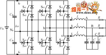
Three-level inverter circuit diagram
Published:2011/9/9 2:24:00 Author:Ecco | Keyword: Three-level inverter
View full Circuit Diagram | Comments | Reading(1251)
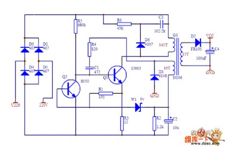
Micro-switching power supply circuit diagram
Published:2011/9/2 1:53:00 Author:Ecco | Keyword: Micro-switching power supply
View full Circuit Diagram | Comments | Reading(10340)
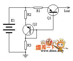
Constant current source circuit diagram ( with online calculator )
Published:2011/9/2 1:51:00 Author:Ecco | Keyword: Constant current source , online calculator
View full Circuit Diagram | Comments | Reading(1497)
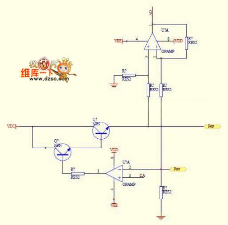
Numerical control constant current source circuit diagram
Published:2011/9/2 1:58:00 Author:Ecco | Keyword: Numerical control , constant current source
View full Circuit Diagram | Comments | Reading(1271)
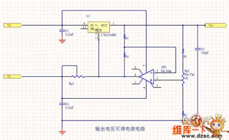
Power Supply circuit diagram with adjustable output voltage
Published:2011/9/9 2:33:00 Author:Ecco | Keyword: Power Supply , adjustable output voltage
View full Circuit Diagram | Comments | Reading(922)
Buck chopper switching power supply circuit diagram
Published:2011/9/9 2:03:00 Author:Ecco | Keyword: Buck chopper, switching power supply
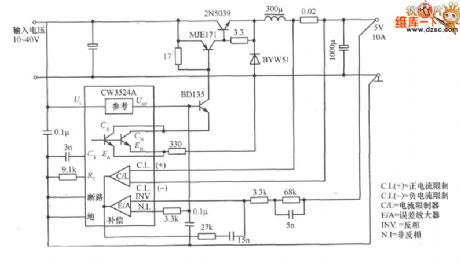
CL(+)=positivecurrent limiting; CL(-)=negative current limiting;C/L=current limiter; E/A=error amplifier; INV=invert; NJ=inverting (View)
View full Circuit Diagram | Comments | Reading(1597)
650W audio power amplifier high-speed power circuit diagram
Published:2011/9/2 1:07:00 Author:Ecco | Keyword: 650W , audio power amplifier , high-speed power
View full Circuit Diagram | Comments | Reading(2933)
Switching 5V, 4W regulated DC power supply circuit diagram
Published:2011/9/9 1:50:00 Author:Ecco | Keyword: Switching , 5V, 4W , regulated DC , power supply
View full Circuit Diagram | Comments | Reading(1831)
A practical simple battery automatic charger circuit
Published:2011/9/14 21:22:00 Author:TaoXi | Keyword: Practical, simple, battery, automatic charger

The circuit principle of the charger is as shown in figure 4-18. The 220V AC city electricity is transformed, rectified and filted by this circuit to output the 20V direct current, and this current charges the battery through the three-port voltage stabilizer. The switching circuit TWH8778 can be used to detect the two-end voltage of the battery.
When the charging starts, the voltage of battery is not enough to conduct the TWH8778, the equivalent circuit is as shown in figure 4-19(a). The constant current charges the battery, the constant current value I0=12.5/R, R is one resistance value of the R1-R4. When the battery voltage increases to the set value, the circuit of figure 4-19(b) is automatically converted into the circuit of 4-19(c).
(View)
View full Circuit Diagram | Comments | Reading(1523)
Simple power supply circuit diagram made by LM317
Published:2011/8/31 21:26:00 Author:Ecco | Keyword: Simple power supply
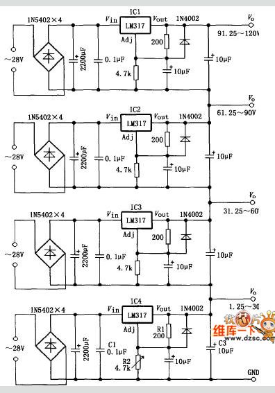
LM317 circuit consists of four components, and four groups of output potential is adjusted by R2. Adjusting R2 can make IC4 output potential be continuously adjustable between the 1.25-30V, while IC1-IC3 connected to it in series output potential also changes resulting in four groups of stable DC voltage between 1.25-120V.
(View)
View full Circuit Diagram | Comments | Reading(3962)
Regulator power supply circuit with adjutable power which is formed by L431
Published:2011/9/15 20:02:00 Author:leo | Keyword: Regulator, power supply, adjutable power
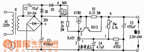
As the picture 1 shows, this is regulator power supply circuit with adjustable power. Its output voltage can reach 36 V and the current can reach 0.1 mA. Its dynamic resistance is 0.22ohm. The picture 2 shows the classic applying of the TL431. The voltages of pin 2 and pin 2 V are the value getting from the format :2.5x(R2十R3)V/R3.If the value of R2 is changed, the output base voltage will also be changed. And the picture 3 shows the classic application of the adjusting tune formed by the base voltage and driving MOFET k790, which can output about 6 A current. This circuit is a simple and safe regulator power supply one. (View)
View full Circuit Diagram | Comments | Reading(1452)
The full-wave rectifier circuit of high-frequency response using balanced output transformer
Published:2011/9/15 0:02:00 Author:Sophia | Keyword: The full-wave rectifier circuit, high-frequency response, balanced output transformer
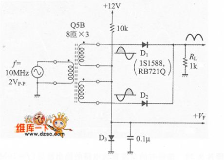
When measuring AC signal levels, the AC circuit is converted into DC, which is called rectifier circuit. But in the rectifier circuit with the diode, the diode forward voltage is very annoying, so a variety of the rectifier circuits appear with the purpuse to remove the effects of the diode forward voltage.
Low-frequency full-wave rectifier circuit is mentioned above, which can be easily achieved through a combination of OP amplifiers and diode, but because the OP amplifier band is very low, we can not achieve the precision rectifier. (View)
View full Circuit Diagram | Comments | Reading(2817)
Feedback resistance circuit diagram of current feedback operational amplifier
Published:2011/9/15 0:01:00 Author:Sophia | Keyword: Feedback resistance, current feedback, operational amplifier
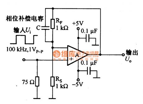
About the current feedback operational amplifier, even if the open-loop gain was changed, the bandwidth also will not be changed. It is often used in video signal amplificaion and the drive circuit of video cable. The diagram is a vedio inphase amplification circuit.
If the broadband high-speed voltage feedback op amp AD844 is adopted, it need to have a phase compensation with the feedback resistor RF and shunt capacitor C. Capacitor C is used to limit the bandwidth, but also have a strong capacity on the capacitive load.
If the current feedback op amp AD844 is adopted and is in parallel with the capacitance C with resistor RF. the circuit will not be stable.
(View)
View full Circuit Diagram | Comments | Reading(1817)
Battery charging circuit composed of MIC5158
Published:2011/9/14 5:56:00 Author:Sophia | Keyword: Battery charging circuit
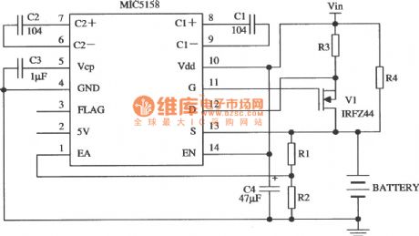
Constant-current charging circuit composed of the MIC5158 is as shown. In the whole process of charging, the circuit provides a constant current (35 mV/R3), until the battery voltage is charged to Vfl:. Vfl is float charge voltage (V). When float voltage is satisfied, MOSFET tube was turned off, and the R4 provides access forthe charge current. (View)
View full Circuit Diagram | Comments | Reading(1491)
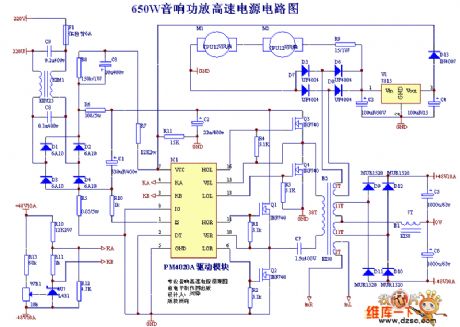
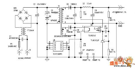
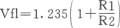
Switching power supply circuit with PM4020A module
Published:2011/9/14 6:01:00 Author:Sophia | Keyword: Switching power supply,
The following drawing uses switching power supply circuit with PM4020A module.PM4020A drive modules is shown by the photos, which can be used to do 200W-1500W switching power supply. PM4060A side can do 1000W-5000W switching power supply. Here is a switching power supply for sound. (View)
View full Circuit Diagram | Comments | Reading(4948)
Regulator DC-DC Circuit and Pin of Power Supply Monitor and its Main Features-MAX743 Regulator
Published:2011/9/13 23:42:00 Author:Zoey | Keyword: Regulator, DC-DC Converter, Pin, Binary Loop,
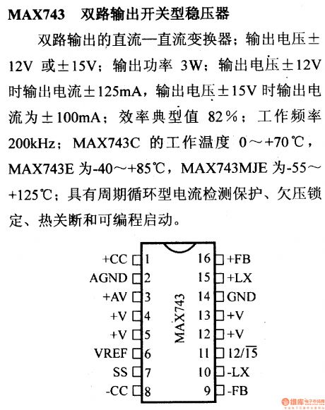
MAX743 binary loop switched regulator refers to the DC-DC converter. Its output voltage is ±12V or ±15V, and relevant output current are ±125mA ,±100mA respectively. Its output power is 3W, typical value of efficiency 82%, working frequency 200 kHz. Working temperature range of MAX743C is 0~+70℃,MAX743E -40~+85℃,MAX743MJE -55~+125℃. The regulator has a periodic circulating current detector, an undervoltage lock, a heater switch and a programmable start.
(View)
View full Circuit Diagram | Comments | Reading(928)
Regulator DC-DC Circuit and Pin of Power Supply Monitor and its Main Features-MAX742 Regulator
Published:2011/9/13 23:43:00 Author:Zoey | Keyword: Regulator, DC-DC Circuit, Pin
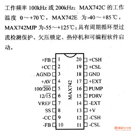
MAX742 binary loop output switched regulator refers to the DC-DC converter. Its output voltage is ±12V or ±15V, output power 3~60W, load current ±2A, output voltage range 4.2~10V, typical value of efficiency 90%.Working frequency 100kHz or 200kHz, working temperature range of MAX742C is 0~+70℃,MAX742MJP is -55~+125℃. The regulator has a periodic circulating current detector, an undervoltage lock, a heater switch and a programmable start.
(View)
View full Circuit Diagram | Comments | Reading(838)
Regulator DC-DC Circuit and Pin of Power Supply Monitor and its Main Features-MAX640/MAX653
Published:2011/9/13 23:45:00 Author:Zoey | Keyword: Regulator, DC-DC converter, Power Supply Monitor
Input voltage range of MAX640/MAX653 DC-DC converter is 4V~11.5V. Output voltage of MAX639 is 5.0V, MAX640 is 3.3V and MAX653 is 3.0V. For the converter, output current can reach 225mA, static working current is 10µA.
(View)
View full Circuit Diagram | Comments | Reading(732)
Regulator DC-DC Circuit and Pin of Power Supply Monitor and its Main Features-MAX1743
Published:2011/9/13 23:45:00 Author:Zoey | Keyword: Regulator, DC-DC Circuit, Pin of Power Supply Monitor, Converter
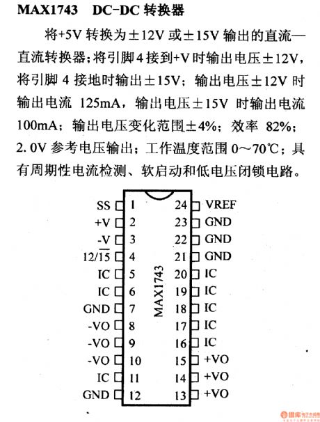
MAX1743 DC-DC converter can convert the voltage from +5V to±12V or to±15V. Connecting pin 4 to +V, andif the output current is 125mA, this converter will output ±12-V voltage; and connecting Pin 4 to the ground, the voltage output will be ±15V, and output current will be 100mA. Its output voltage range is±4%, efficiency 82%, reference voltage output 2.0V, working temperature range 0~70℃. This converter has circuits for periodic current detection, soft-start and low-voltage lock. (View)
View full Circuit Diagram | Comments | Reading(977)
| Pages:56/291 At 204142434445464748495051525354555657585960Under 20 |
Circuit Categories
power supply circuit
Amplifier Circuit
Basic Circuit
LED and Light Circuit
Sensor Circuit
Signal Processing
Electrical Equipment Circuit
Control Circuit
Remote Control Circuit
A/D-D/A Converter Circuit
Audio Circuit
Measuring and Test Circuit
Communication Circuit
Computer-Related Circuit
555 Circuit
Automotive Circuit
Repairing Circuit