
Pulse Signal Generator
Index
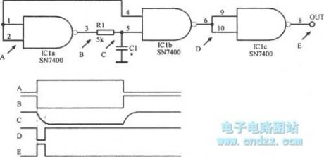
Square wave burst
Published:2013/3/27 3:30:00 Author:Ecco | Keyword: Square wave burst
Square wave burst is shown as figure.
(View)
View full Circuit Diagram | Comments | Reading(1457)
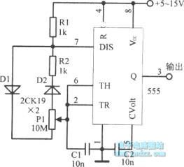
1μs pulse circuit
Published:2013/3/25 2:16:00 Author:Ecco | Keyword: 1μs pulse
1μs pulse circuit is shown as figure.
(View)
View full Circuit Diagram | Comments | Reading(1277)
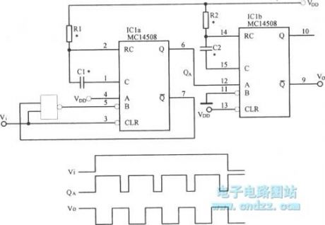
Programmable pulse width generator circuit
Published:2013/3/19 3:42:00 Author:Ecco | Keyword: Programmable, pulse width generator

Programmable pulse width generator circuit is shown as figure.
(View)
View full Circuit Diagram | Comments | Reading(1095)
Configurable pulse width generator circuit
Published:2013/3/19 2:32:00 Author:Ecco | Keyword: Configurable , pulse width generator

Configurable pulse width generator circuit is shown as figure.
(View)
View full Circuit Diagram | Comments | Reading(1343)
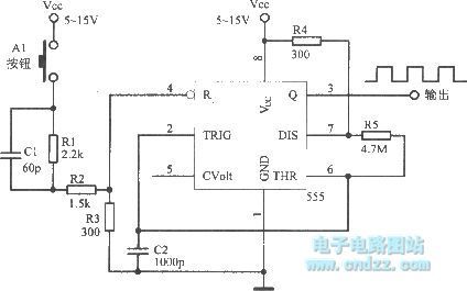
Pulse keying pulse source with monostable trigger
Published:2013/3/19 2:17:00 Author:Ecco | Keyword: Pulse keying, pulse source , monostable trigger
Pulse keying pulse source with monostable trigger is shown as figure.
(View)
View full Circuit Diagram | Comments | Reading(970)
Asynchronous pulse synthesis circuit
Published:2013/3/19 2:16:00 Author:Ecco | Keyword: Asynchronous pulse synthesis
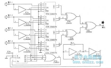
Asynchronous pulse synthesis circuit is shown as figure.
(View)
View full Circuit Diagram | Comments | Reading(1175)
Audio short pulse sequence circuit
Published:2013/3/19 2:12:00 Author:Ecco | Keyword: Audio, short pulse sequence
Audio short pulse sequence circuit is shown as figure.
(View)
View full Circuit Diagram | Comments | Reading(949)
Pulse forming circuit with integral circuit
Published:2013/3/12 3:32:00 Author:Ecco | Keyword: Pulse forming , integral circuit
Pulse forming circuit with integral circuit is shown as figure.
(View)
View full Circuit Diagram | Comments | Reading(1117)
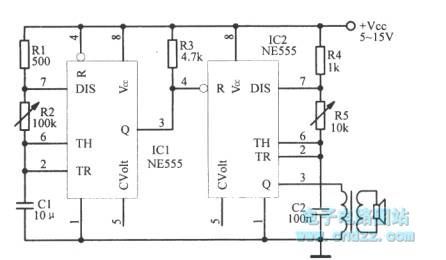
0.5 seconds tone burst circuit
Published:2013/3/12 3:29:00 Author:Ecco | Keyword: 0.5 seconds , tone burst circuit
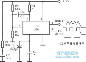
0.5 seconds tone burst circuit is shown as figure.
(View)
View full Circuit Diagram | Comments | Reading(956)
The pulse generator with wide range of adjustable duty
Published:2013/2/21 0:48:00 Author:Ecco | Keyword: pulse generator , wide range , adjustable duty
View full Circuit Diagram | Comments | Reading(1321)
S / R ( set / reset ) pulse generator circuit ( integrated magnetic field sensor HMC1001/1002 )
Published:2012/10/7 21:39:00 Author:Ecco | Keyword: S / R , set , reset, pulse generator, integrated, magnetic field sensor
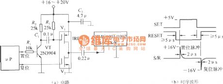
S / R pulse is set / reset pulse, of which amplitude depends on the measurement sensitivity of the MR sensor. For example, Tesla meter is composed of HMC1001/1002, when the minimum measurable flux density is 50nT, the amplitude of pulse current is required not less than 3A; when the minimum measurable flux density is 10 nT, the pulse current amplitude is not less than 4A. The higher measurement sensitivity is, the higher pulse current amplitude is. The circuit uses a microprocessor circuit to generate the S / R pulse, and the circuit is shown as the figure. This circuit uses +16 ~ +20 V power supply, and the pulse current can be more than 4A.
(View)
View full Circuit Diagram | Comments | Reading(2853)
12 coil Pulse Monopole/Generator
Published:2012/9/16 21:50:00 Author:Ecco | Keyword: 12 coil, Pulse Monopole, Generator
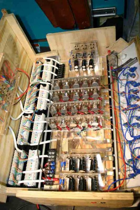
Fully functional Bedini motor pulse charger powered by micro-controller. All variables (coil sensitivity thresh-hold and motor power (current) consumption) controlled by software program. I can manipulate triggering of motor and triggering of cap pulse disharge. Results have convinced me this is the cheaper way to build and experiment. I haven't blown any components yet with this experiment with no protection Neon (Ne2) on transistor. (View)
View full Circuit Diagram | Comments | Reading(2222)
Delayed Pulse Generator
Published:2012/9/9 20:31:00 Author:Ecco | Keyword: Delayed , Pulse , Generator
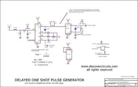
This circuit generates a short 10ms pulse 15 minutes after a ?start? pushbutton switch is activated. (added 12/04)
Source: discovercircuits (View)
View full Circuit Diagram | Comments | Reading(0)
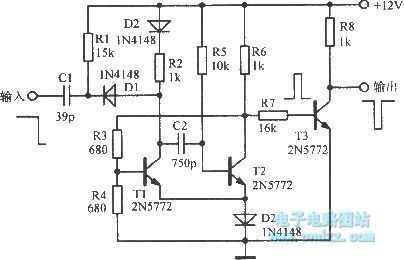
Pulse generator circuit using two complementary transistors
Published:2011/10/31 1:58:00 Author:May | Keyword: Pulse generator , two complementary transistors
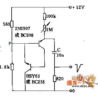
It usestwo complementary transistorsto produce pointed pulse with theamplitude in 8V, rise time in 50nS+. This circuit pulse intermission is 1.4ms at the situation of charging capacitance is 10nF and 1M potentiometershort-circuited, and the weakening or decreasing capacitance value can make the pulse intermission increase or decrease. If 820Ω resistor isconnected at the emitter of NPN transistor instead of series with capacitor, it will get sharp pulse output.
(View)
View full Circuit Diagram | Comments | Reading(4275)
The pulse generator circuit with sharp pulse and sawtooth pulse
Published:2011/11/27 21:05:00 Author:Ecco | Keyword: pulse generator , sharp pulse , sawtooth pulse
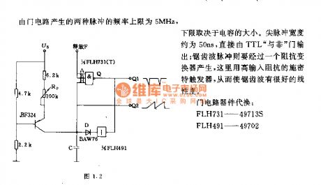
The upper limit of the two pulses' frequency generated by the gate circuit is 5MHZ, the lower limit depends on the size of the capacitor . Sharp pulse width is about 50ns, which is output directly from TTL and non gate; sawtooth pulse is generated by impedance converter, which is a Schmitt trigger with high input impedance, so that it has a good sawtooth linearity . Gate device substitution : FLH731-49713S, FLH491-49702.
(View)
View full Circuit Diagram | Comments | Reading(1120)
The pulse generator ( Figure 1.6 ) circuit with output multiple waveforms
Published:2011/11/27 20:49:00 Author:Ecco | Keyword: pulse generator , multiple waveforms
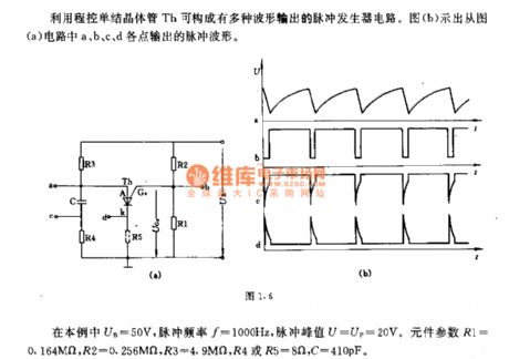
It uses the programmable unijunction transistor Th to form a pulse waveform generator circuit which can output multiple waveforms. Figure (b) shows the pulse waveforms output by a, b, c, d points which are shown in Figure (a) circuit. In this case, UB = 50V, pulse frequency f = 1000Hz, pulse peak U = UP = 20V. Component parameters R1 = 0.164MΩ, R2 = 0.256MΩ, R3 = 4.9MΩ, R4 or R5 = 8Ω, C = 410pF.
(View)
View full Circuit Diagram | Comments | Reading(1757)
Pulse generator circuit with variable pulse width
Published:2011/11/28 21:24:00 Author:Ecco | Keyword: Pulse generator, variable pulse width
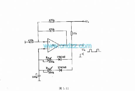
Pulse frequency depends on the size of the capacitor C , and it can use 0.1μF or other values according needings. 12KΩ resistor is the load resistor for op-amp open collector. (View)
View full Circuit Diagram | Comments | Reading(1668)
Sharp pulse generator circuit
Published:2011/11/27 20:38:00 Author:Ecco | Keyword: Sharp pulse generator
The circuit shown in Figure (a) can produce 2μs sharp pulse. Repetition frequency is determined by the following equation f = 1/2.3C kHz. And C's unit is μF. In the circuit shown in Figure b, adjusting the potentiometer RP can get 1:20 available frequency range . Of course , adjusting the size of the input voltage Ust can change the frequency. Gate device substitution : FLH25J-4700.
(View)
View full Circuit Diagram | Comments | Reading(951)
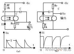
Schematic and applied circuit diagram of pulse circuit composed of photoelectric coupler
Published:2011/9/9 7:54:00 Author:Vicky | Keyword: Schematic and applied circuit diagram, pulse circuit composed of photoelectric coupler
picture1
picture2
When Ec is just on in picture 1(a), Up increases when C is charging. When UF≈1, luminous diode and then the triode become saturate, and output Uo≈Ec.
When triode becomes saturate, C discharges (through two route: C→F→E1→Er and C→RF→+Ec→R ). Uo becomes lower. The diode stops when c discharges to a certain degree. The triode stops subsequently after moving all the memory electric charge, and uo becomes zero. Power Ec charges C again after triode stops, and the above process repeats again. Thus the peak output wave is obtained, and the cycle is (when RF》Re ): T=C(RF+Re)In2 (View)
View full Circuit Diagram | Comments | Reading(1139)
Complementary tube pulse circuit principle and applied circuit diagram
Published:2011/9/9 7:51:00 Author:Vicky | Keyword: complementary tube pulse circuit
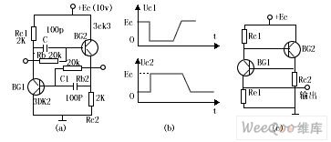
(picture1)
Complementary tube bistable state circuit is shown in picture1(a). When the power is on, if no triggering signal works, the two tubes stop working and the state is in a stable state because the collector current is extramely small, and the end voltage of RC1, and Rc2 (bias current provided to the two tubes) is also very small.
When the trigger pulse is working, suppose that BG1 becomes amplified from static, and leads to the process of avalanche-type positive feedback. Soon the two tubes become saturate, and are in another stable state. Capacitance C1 is speed-up capacitor. From picture1(b), we can see that uc1 goes down to zero sharply from Ec, while Uc2 zooms up to Ec from zero. (View)
View full Circuit Diagram | Comments | Reading(1109)
| Pages:1/3 123 |
Circuit Categories
power supply circuit
Amplifier Circuit
Basic Circuit
LED and Light Circuit
Sensor Circuit
Signal Processing
Electrical Equipment Circuit
Control Circuit
Remote Control Circuit
A/D-D/A Converter Circuit
Audio Circuit
Measuring and Test Circuit
Communication Circuit
Computer-Related Circuit
555 Circuit
Automotive Circuit
Repairing Circuit