
Signal Processing
Index 160
Simple high & low frequency signal generator circuit
Published:2011/6/21 9:14:00 Author:TaoXi | Keyword: Simple, high, low, frequency, signal generator
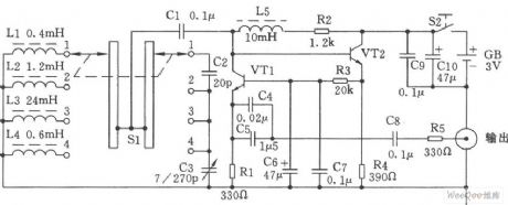
The simple high & low frequency signal generator circuit is as shown in the figure. You can change the inductance value of the LC resonance loop by using the band switch Sl, so we can change the frequency range of the high-frequency oscillation. This device has four stages:
The first stage is 0.4~2MHz;The second stage is 2~10MHz;The third stage is 9~45MNz;The fourth stage is 60~110MHz.
Components selection:
The VTl and VT2 use the NPN silicon tube (fT≥800MHz, β≥100) such as the 9018 and C535.etc. The resistance uses the 1/8W carbon membrane resistance. The capacitance C5 uses the monolithic capacitor, the other capacitances use the ceramic capacitor. The L2, L3, L4 and L5 use the high-frequency magnetic inductor, or you can wind it by yourself. The Ll uses the Φ0.6mm high strength varnished wire. The Sl uses the double-blade four-throw wave-band switch.
(View)
View full Circuit Diagram | Comments | Reading(1505)
Potentiometer control digital oscillator circuit
Published:2011/6/26 20:54:00 Author:TaoXi | Keyword: Potentiometer control, digital oscillator
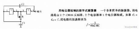
The potentiometer control digital oscillator circuit is designed as one kind of very simple oscillator that is composed of two CMOS inverters, two capacitors and a potentiometer. If C1=C2=C, the oscillation frequency of this circuit is f=1/4ln2RC.
(View)
View full Circuit Diagram | Comments | Reading(758)
Voltage control annular oscillator circuit
Published:2011/6/26 20:49:00 Author:TaoXi | Keyword: Voltage control, annular oscillator
The voltage control annular oscillator circuit changes the oscillation frequency by changing the charging and discharging voltage final value of the timing capacitance C.
(View)
View full Circuit Diagram | Comments | Reading(764)
Voltage control TTL symmetric harmonic oscillator circuit
Published:2011/6/26 19:13:00 Author:TaoXi | Keyword: Voltage control, TTL, symmetric, harmonic oscillator
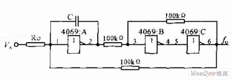
The voltage control TTL symmetric harmonic oscillator circuit uses the external control voltage VA to control the Inverter input voltage. The output frequency of the circuit is proportional to the VA, and it has wide adjustment range. If the VA change from 1.4V to 1.8V, the oscillation frequency is from 666KHz to 1.43MHz. The circuit (b) increases the bias resistors R1, R2 and R3, R4 than circuit (a). The D1 and D2 are the protection diodes. When the VA is from 0V to 10.5V, the frequency changes from 6.54MHz to 4.76MHz.
(View)
View full Circuit Diagram | Comments | Reading(614)
Voltage control oscillator circuit of the practical CMOS integrated circuit
Published:2011/6/26 4:11:00 Author:TaoXi | Keyword: Voltage control oscillator, practical, CMOS, integrated circuit
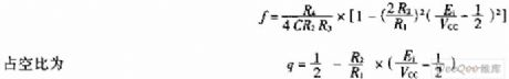
The voltage control oscillator which uses the CMOS integrated circuit always has the positive and negative power supplies, but the CMOS integrated circuit only uses one power supply. When the input voltage is 1/2 of the power supply voltage VCC, the oscillation frequency is the maximum. When the input voltage is higher than 1/2VCC or lower than 1/2VCC, the oscillation frequency is:
(View)
View full Circuit Diagram | Comments | Reading(491)
Two-channel asynchronous output waveform generator circuit
Published:2011/6/25 7:18:00 Author:TaoXi | Keyword: Two-channel, asynchronous output, waveform generator
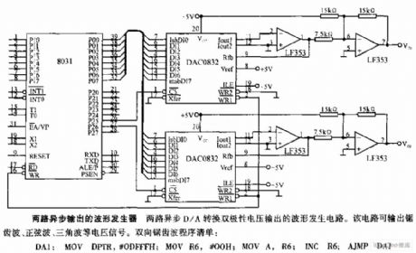
The two-channel asynchronous output waveform generator circuit is designed as one kind of waveform generator circuit that has the two channels of D/A conversion dual polarity voltage output. This circuit can output the sawtooth wave, the sine wave and the triangular wave.
(View)
View full Circuit Diagram | Comments | Reading(849)
12.85MHZ changeable pulse width generator circuit
Published:2011/6/25 6:27:00 Author:TaoXi | Keyword: 12.85MHZ, changeable pulse, width generator
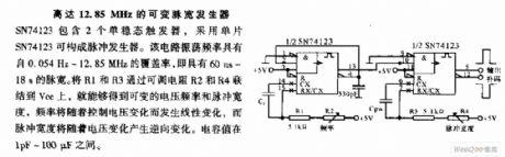
The 12.85MHZ changeable pulse width generator circuit: the SN74123 includes two monostable triggers, it uses the single chip SN74123 to form the pulse generator. The frequency range of this circuit is 0.054Hz-12.85MHz, so it has the pulse width range of 60ns-18s. If you connect the R1 and R3 to the Vcc through the adjustable resistors R2 and R4, so you get the variable voltage frequency and pulse width, the frequency will change with the control voltage, the pulse width will reversely change with the voltage. The capacitance value is in the range of 1pF-100uF.
(View)
View full Circuit Diagram | Comments | Reading(824)
Multi-function numerical control waveform generator circuit
Published:2011/6/25 5:52:00 Author:TaoXi | Keyword: Multi-function, numerical control, waveform generator
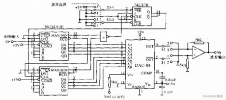
The multi-function numerical control waveform generator circuit is as shown in the figure, it is designed as one kind of digital waveform generator application circuit that can produce the triangular wave and the sawtooth waveform. In the figure, the 8-bit reversible counter is composed of two 4-bit reversible counter SN74L191, the increasing or decreasing count output is used as the input of D/A converter, the output voltage Vo is the gradually increasing or decreasing voltage, it changes linearly. When the manual switch S3 is in position 2 , the trigger's output Q=1, the counter counts diminishly, and it outputs the negative sawtooth wave; when the manual switch S3 is in position 3 , Q=0, it outputs the positive sawtooth wave.
(View)
View full Circuit Diagram | Comments | Reading(1062)
Square wave clock circuit
Published:2011/6/25 5:34:00 Author:TaoXi | Keyword: Square wave, clock circuit
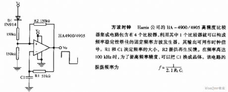
Square wave clock: The HA-4900/4905 high precision comparator integrated circuit which is produced by the Harris company has four comparators, you can form the fixed frequency square wave generator with good frequency stability by using only one comparator, the output can be used as the clock signal. The frequency is decided by the R1 and C1, R2 supplies the regeneration feedback. When the frequency is 100kHz, in order to improve the frequency precision, we can change C1 into the crystal. The oscillation frequency of this circuit f=1/2.1R1C1.
(View)
View full Circuit Diagram | Comments | Reading(710)
1kHz oscillating circuit
Published:2011/6/13 7:49:00 Author:Christina | Keyword: 1kHz, oscillating circuit
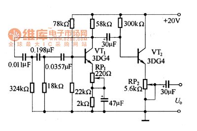
As the figure shows, the oscillating circuit is composed of three RC phase shifting networks with the impedances reduce in turn, the oscillation frequency is 1kHz, the output amplitude is 6V. By adjusting RP1, you can improve the waveform distortion. The oscillation signal is output by the emitter follower which is composed of the VT2.
Figure The 1kHz oscillation circuit
(View)
View full Circuit Diagram | Comments | Reading(748)
465kHz intermediate frequency signal generator circuit
Published:2011/6/13 7:44:00 Author:Christina | Keyword: 465kHz, intermediate frequency, signal, generator
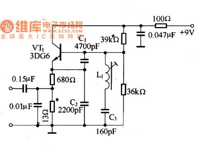
The three-point capacitance oscillator circuit is as shown in the figure, it can produce the 465kHz intermediate frequency signal. In the figure, the resonance loop is composed of the C1, C2, C3 and L1, because the capacity of C1, C2 is larger than the capacity C3, so the oscillation frequency is decided by the C3 and L1
Figure The 465kHz intermediate frequency signal generator circuit
(View)
View full Circuit Diagram | Comments | Reading(1711)
local oscillator circuit with 465KHz difference frequency
Published:2011/6/18 22:38:00 Author:Nancy | Keyword: local oscillator, 465KHz, difference frequency
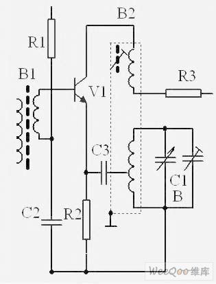
V1 is a frequency converter tube with oscillation and frequency mixing functions. The local oscillator circuit forms a transfomer feedback oscillator composed by oscillation transformer B2 and adjustable capacitor C1b, the oscillator frequency is mainly decided by L4 and C1b, the local oscillator signal is connected to V1 base-emitter though C2 and C3, the self-excited oscillation signal is coupled to oscillation loop by feedback coil and then sent back to V1 base-emitter though C3 and C2, it is amplified circularly and forms oscilltion. The input tuning signal and local oscillation signal are added to the triode simultaneously, then the sum frequency, multiplication frequency and differential frequency of two frequencies will be produced at the emitter of the triode using the non-linear characteristic of the triode. (View)
View full Circuit Diagram | Comments | Reading(1125)
The electric clock circuit
Published:2011/6/25 1:59:00 Author:qqtang | Keyword: electric clock
View full Circuit Diagram | Comments | Reading(721)
The FET crystal oscillator circuit-inductance feedback oscillator circuit
Published:2011/6/18 2:21:00 Author:Seven | Keyword: FET, crystal oscillator, inductance
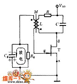
The composition of the circuit: FET T, LC parallel circuit, the fence bias voltage consisting of Rg and Cg is shown in the figure.
(1) the phase balance condition: it is judged in the instant polarity method(2) the amplitude balance condition is (View)
View full Circuit Diagram | Comments | Reading(587)
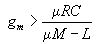
The FSK signal demodulation circuit composed of the digital phase-lock
Published:2011/6/24 2:38:00 Author:Seven | Keyword: FSK, signal demodulation, phase-lock
In Figure 7-2 is the FSK signal demodulation circuit composed of the digital phase-lock. The circuit consists of 2 oscillators with different frequencies, i.e crystal oscillators X (the frequency is 983.04KHz) and X2 (the frequency is 1.2288MHz) compose the oscillator, and X2 consists of the frequency converting circuit 74HC157, frequency splitting circuit MC14040B, phase comparator MCI4030B and so on. The output signal of the comparator MC14030B is delivered into the converting circuit 74HC157, by adjusting the ratio of frequency 1 and frequency 2, the output frequency can be any one between the two frequencies.
(View)
View full Circuit Diagram | Comments | Reading(3024)
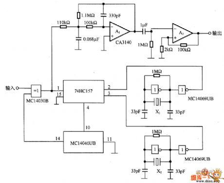
The 1200Hz~100kHz clock signal source circuit
Published:2011/6/24 3:14:00 Author:Seven | Keyword: 1200Hz~100kHz, clock signal source
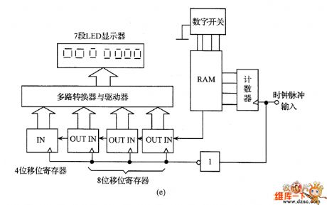
In figure 6-39 is the 1200Hz~100kHz clock signal source circuit, of which figure (b) is the circuit frame circuit, see from the frame circuit, we know that the counter counts the output pulse of the oscillator, and then the pulse is compared with the digital switch set value by the comparator, if the pulse reaches the set value, the gate circuit will be closed and the pulse is prevented from inputting. Figure (a) is the clock signal source circuit, in the circuit, the oscillator is the standard clock pulse generator SPG8651B, in the chip is the crystal oscillator circuit, the pin arrangement is shown in figure (c).
(View)
View full Circuit Diagram | Comments | Reading(1209)
The transistor diode bridge rectifier circuit
Published:2011/6/23 22:16:00 Author:Seven | Keyword: transistor diode, bridge rectifier
The transistor diode bridge rectifier circuit is shown as above.
(View)
View full Circuit Diagram | Comments | Reading(2076)
Matching circuit and signal receiving circuit diagram
Published:2011/6/20 6:26:00 Author:Lucas | Keyword: Matching circuit , signal receiving
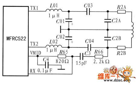
Internal receiver circuit works rely on the responding signals of card having modulation function on the bilateral area of sub-carrier. VMID signal produced by the internal circuit of MFRC522 is used as the bias of RX pin input signal. It needs to connect a capacitor C4 between VMID and GND for stabilizing VMID output. Receiver circuit needs to be connected a voltage divider circuit between the RX and VMID. The matching circuit and the signal receiving circuit is shown as the chart. The figure includes EMC low pass filter (L01, L02, C01, C02), receiver circuit (R66, C3, R65, C4), antenna matching circuit (C03, C04 , C2A, C2B, R2A, R2B) and antenna.
(View)
View full Circuit Diagram | Comments | Reading(2269)
AC high voltage generator
Published:2011/6/20 6:46:00 Author:Lucas | Keyword: AC, high voltage , generator
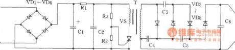
The chart shown as the chart is the AC high voltage generator. It uses AC 220V input directly , and it has the features of with small size, high efficiency, long working time, high output current and so on. A type can work continuously for longer than five minutes, B type can work in long hours. Component selection: VD1 ~ VD4 use 1N4007 diodes, C1 uses 10μF/400V dielectric capacitor; C2 uses nonpolar 0.47μF/450V capacitor; R1 uses the 10k/5W resistor; R2 uses the 1/8W 10K resistor, R3 uses the 1/8W 1.6MΩ ~ 1.8MΩ resistor, VS uses the 3A/400V unidirectional thyristor, C3 ~ C5 use high pressure lOOp/14kV ceramic capacitors, C6 selects the lOOOp/40kV capacitor with engineering plastic shell.
(View)
View full Circuit Diagram | Comments | Reading(975)
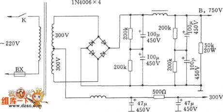
Low-power high-performance high-voltage generator
Published:2011/6/20 6:18:00 Author:Lucas | Keyword: Low-power , high-performance, high-voltage , generator
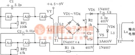
The chart shown as the chart is the low-power high-performance high-voltage generator. It uses CMOS integrated circuits, it has the features of simple current, small operating current (about several hundred mA), reliable working. It is suitable for electric batons, electric fences and many other uses.
(View)
View full Circuit Diagram | Comments | Reading(661)
| Pages:160/195 At 20141142143144145146147148149150151152153154155156157158159160Under 20 |
Circuit Categories
power supply circuit
Amplifier Circuit
Basic Circuit
LED and Light Circuit
Sensor Circuit
Signal Processing
Electrical Equipment Circuit
Control Circuit
Remote Control Circuit
A/D-D/A Converter Circuit
Audio Circuit
Measuring and Test Circuit
Communication Circuit
Computer-Related Circuit
555 Circuit
Automotive Circuit
Repairing Circuit