
Amplifier Circuit
Index 19
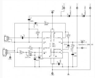
50W amplifier based LM3886TF
Published:2013/3/12 1:16:00 Author:Ecco | Keyword: 50W amplifier
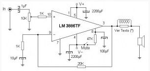
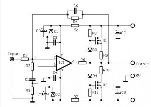
This 50W amplifier circuit is designed for quad power stage on computers equipped with sound cards MonsterSound Diamond MX300. With this circuit we get 200W output power with a total harmonic distortion of less than 0.01%. Somewhat classified as High-End Audio.
The audio signal from the sound card enters the operational amplifier by pin 10 (non-inverting input). A 1μF capacitor passes only the audio signal, blocking the DC component that may exist. A 10K potentiometer (optional) lets you adjust the input limit. At the output a 20K resistor performs the feedback through the inverting input while a set RL power output coupled to the speaker. This set consists of a coil of 10 to 15 turns of wire 1.5mm on a resistance of 10 ohms / 2 watt. Two electrolytic decouple the power supply and a jumper controls the mute (silence) which is activated by opening the switch. The 100μF capacitor with the 47K resistor act as input delay, avoiding noise when connecting the power.
(View)
View full Circuit Diagram | Comments | Reading(3377)
90 W audio power amplifier based on transistor
Published:2013/3/12 1:15:00 Author:Ecco | Keyword: 90 W, audio power amplifier, transistor
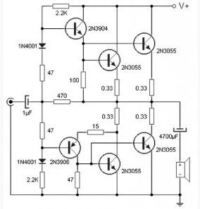
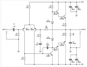
Using only four transistors in the quasi-complementary amplifier configuration, thistransistor power amplifier circuit can deliver 90W of power into 4 ohm loads and at low cost.
As shown in the transistor power amplifier circuit there are no expensive components in this circuit, except the power transformers and speakers. As shown in the diagram there are no expensive components in this circuit, except the power transformers and speakers. Input stage is formed by this two current driver directly raised a pair of transistors of the output stage. Transistor level end (2N3055) mounted on a heat sink to keep the lifetime of these devices. Supported by one source (of 80Vcc) at the output of the final stage, before the speaker, a capacitor is placed to block DC current, and just skip the audio signal. The power supply circuit 90 W audio power amplifier must be sufficient to provide current 1.5A per channel audio. Thus the power required to operate the stereo 3A and 6A is required for the four audio channels.
(View)
View full Circuit Diagram | Comments | Reading(12170)
Portable Sound level meter
Published:2013/3/12 1:14:00 Author:Ecco | Keyword: Portable , Sound level , meter
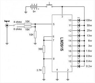
These Sound level meter devices can directly determine the power delivered by the amplifier to the cabinet or Loudspeaker. Operated through a common 9V battery makes it portable and easy to carry.
As shown in the Sound level meter schematic diagram of the entire system is in the integrated circuit LM3915, and beyond that there are only a a few passive components. Because the impedance of the speaker in which the measurements were made affecting the outcome, and therefore provided a button to select the load impedance, it may be 4 or 8 ohm.
These Sound level meter devices must be connected, if possible, the terminal itself and baffle not on the amplifier to prevent effect of cable length and voltage drop that is not covered under the measure.
(View)
View full Circuit Diagram | Comments | Reading(1531)
100W Audio Amplifier with Integrated Circuit
Published:2013/3/12 1:13:00 Author:Ecco | Keyword: 100W , Audio Amplifier, Integrated Circuit
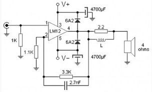
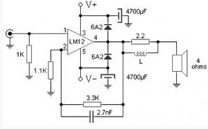
Almost all of the audio power amplifier if using integrated circuit amplifier as circuit shown here which is use M12CLK is an power operational amplifier. It allows an output stage operating at even 2 ohms impedance and gain power 150W. For stability and safety this system decided to make it work with 4 ohm speakers so we gain 100W RMS power.
(View)
View full Circuit Diagram | Comments | Reading(1937)
70W FM amplifier
Published:2013/3/12 1:12:00 Author:Ecco | Keyword: 70W, FM amplifier

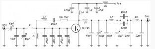
The heart of this stage is an RF transistor (the BLY90) which, together with the classical passive components in such systems, performs the function of amplifying the radio signal present at its base to deliver to its collector.
(View)
View full Circuit Diagram | Comments | Reading(1354)
100W bridge amplifier based TDA7294
Published:2013/3/12 1:10:00 Author:Ecco | Keyword: 100W , bridge amplifier
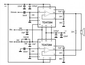
This 100W bridge amplifier circuit can increase the power level of the audio signal from a source that has a LINE output type.
(View)
View full Circuit Diagram | Comments | Reading(4438)
20W stereo amplifier based LM1876
Published:2013/3/12 1:09:00 Author:Ecco | Keyword: 20W , stereo amplifier
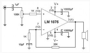
This two-channel amplifier provides power to 20 watts RMS from two line inputs. Ideal for use in computers since its price / performance / complexity is optimal.
In the 20 watt stereo amplifier circuit observed only one stage of the system because the circuit stereo, second channel are identical. The figures in parentheses are equivalent to the terminal for second channel. The core of this project is the integrated circuits from National Semiconductor, the LM1876, which provides two power operational amplifier with mute and standby function.
(View)
View full Circuit Diagram | Comments | Reading(2510)
Multidirectional microphone amplifier
Published:2013/3/12 0:57:00 Author:Ecco | Keyword: Multidirectional microphone , amplifier

This Multidirectional microphone amplifier circuit is often used in a panel discussion or a meeting room to capture the audio from all the partners without the need to give each microphone. Placing this in the middle of the table captures audio from each through which is formed by four electret capsules with a level control for each individual reception.
We can say that this Multidirectional microphone circuit consists one side of electret four modules, each of them provide power to the capsule through 10K resistor, DC blocked through 1μF capacitor and the resulting AF signal is received at the end of the potentiometer which serves as a reception setting. 100K resistors and transistors form a network FET preamp and summing several signals, which can be applied without any problems on the line input as the microphone channel of the console.
(View)
View full Circuit Diagram | Comments | Reading(1562)
10 W Audio Amplifier based TDA 2003
Published:2013/3/12 0:55:00 Author:Ecco | Keyword: 10 W, Audio Amplifier
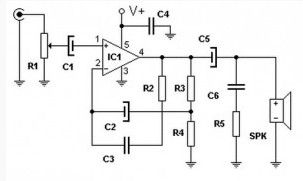
With only one active integrated circuit TDA 2003 as component this circuit can provide up to 10W of audio power to the load which can be between 2 and 8 ohm.
(View)
View full Circuit Diagram | Comments | Reading(2090)
High quality 10W Audio Amplifier
Published:2013/3/12 0:54:00 Author:Ecco | Keyword: High quality, 10W , Audio Amplifier
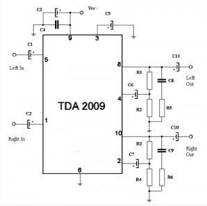
The main components of this high quality 10W stereo power amplifier circuit is uses TDA 2009 which is a class AB Audio Power Amplifier. IC TDA 2009 is specifically designed for high quality stereo applications such as HI-FI and music center.
As you can see on the circuit, this class AB amplifier IC requires only a few external components. And this 10 W audio amplifier circuit is also very easy to build. This 10W stereo amplifier circuit requires a stable power supply with a voltage of 18 V and 1A current needs.
(View)
View full Circuit Diagram | Comments | Reading(1998)
100 W valve audio amplifier
Published:2013/3/12 0:53:00 Author:Ecco | Keyword: 100 W , valve, audio amplifier
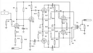
This is a valve audio amplifier circuit which can provide power up to 100W.
(View)
View full Circuit Diagram | Comments | Reading(1965)
80W power amplifier circuit with TDA7294
Published:2013/3/12 0:51:00 Author:Ecco | Keyword: 80W , power amplifier
Power Amplifier based tda7294 from ST microeletronics, you can gain power up to 100W in a single chip, for stereo unit, use similar two circuits. This circuit is based on the manufacturer’s datasheet for tda7294 typical application usage. Amplifier is ready to work with a powerful signal source, if necessary, use an opamp pre-amplifier.
This type of 80w power amplifier circuit chip is ideal for surround sound systems. Since this is quite compact and can be used for independent amplifier for each speaker. In this way it can be upgraded to share source to support all of the connected amplifier.
(View)
View full Circuit Diagram | Comments | Reading(2173)
Audio Power amplifier (30W)
Published:2013/3/11 21:03:00 Author:Ecco | Keyword: Audio Power amplifier , 30W
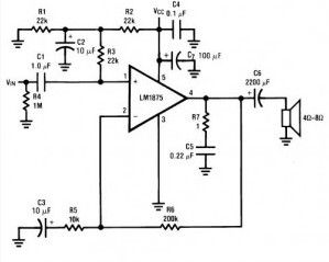
The following circuit uses LM1875 audio amplifier capable of delivering up to 30W RMS power into 8 ohm speakers with a total harmonic distortion (THD) 1%.
(View)
View full Circuit Diagram | Comments | Reading(2259)
12W FET audio amplifier
Published:2013/3/11 21:02:00 Author:Ecco | Keyword: 12W , FET, audio amplifier
This is a small 12W power amplifier on a load of 8 Ω, that combining the NE5534 integrated technology with transistors as V-MOSFET output stage get an excellent sound quality. The input sensitivity is 3V rms maximum, the distortion factor is 0.002% at 1 kHz, and frequency response is 15 Hz to 100 kHz. (-3dB).
(View)
View full Circuit Diagram | Comments | Reading(3388)
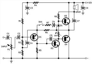
75W Transistor Audio Amplifier
Published:2013/3/11 21:00:00 Author:Ecco | Keyword: 75W , Transistor, Audio Amplifier
It is simple to build an amplifier, using the standard and stable and reliable. The 75 W amplifier circuit presented here is capable of driving 4 ohm, but, although used in 4 ohms, this amplifier has very few errors.
To be aware that there are no short-circuit output, so that when the speaker short, while the amplifier is working (with signal), there is a very real danger that may damage the transistor.
(View)
View full Circuit Diagram | Comments | Reading(5998)
100 W audio amplifier based LM12CLK
Published:2013/3/11 20:59:00 Author:Ecco | Keyword: 100 W , audio amplifier
The 100W audio power amplifier is powered by the integrated circuit LM12CLK which is operational power amplifier. The monolithic IC can deliver 80W of sine wave power into 4Ω load with 0.01% distortion. Power bandwidth is 60 kHz .. Important features of IC LM12CLK include : controlled turn on, overvoltage shutdown, output-current limiting, dynamic safe-area protection, thermal limit, Input protection
This amplifier allows to operate at 2 Ω output impedance and gain 150W of power. For savety and system stability, this 100W audio amplifier is designed to work with 4-Ω speaker to gain the power of the 100W RMS.
(View)
View full Circuit Diagram | Comments | Reading(1953)
12W amplifier circuit based 741 Op Amp
Published:2013/3/11 20:57:00 Author:Ecco | Keyword: 12W amplifier , Op Amp
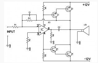
This Amplifier is 12 watts and to operate this is use source of dual symmetric ± 12 volt. The 741 provides the required gain while the speaker unit driven by complementary Darlingtons T1, T2 and T3, T4.
Input signal to the Darlington comes from the feed current 741. Since R6 is connected to earth, positive or negative current signal is also going through R4 or R5. The voltage drop across this resistance serves as the input signal to the transistor pairs. A common dc negative feedback from the collector junction with T2 and T4 stabilize the DC circuit and the junction point is maintained at zero volts. So, there is no coupling capacitor needed for the speaker.
(View)
View full Circuit Diagram | Comments | Reading(1862)
2 watts amplifier schematic diagram
Published:2013/3/11 20:54:00 Author:Ecco | Keyword: 2 watts, amplifier
The amplifier is designed for independent in a small speaker box. Can support to Walkman, Mini-Disc and CD players, computers, and similar devices with line or headphone output. Of course, in many cases, you will need to create two units for stereo.
(View)
View full Circuit Diagram | Comments | Reading(1375)
Vacuum Tube Stereo Microphone Preamp
Published:2013/3/10 22:12:00 Author:Ecco | Keyword: Vacuum Tube, Stereo Microphone, Preamp
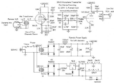
This microphone preamplifier is designed to interface a dynamic microphone directly to a computer's sound card input. It can also be used as a mic preamp for analog recorders. The circuit is configured like a mixing board input strip so that each microphone has its own bass and treble cut/boost control. With a larger power supply, this preamp could easily be doubled to provide four channels.
The project was inspired by your author's attempts to record live audio using various small solid-state mixing boards with built-in mic preamps. The preamps all produced high levels of hiss and a quieter mic preamp was desired. The hiss problem is multiplied when making a multi-track audio recording since each new track adds to the combined hiss level.
(View)
View full Circuit Diagram | Comments | Reading(4059)
Low Power 6U8A Vacuum Tube Audio Amp
Published:2013/3/10 22:11:00 Author:Ecco | Keyword: Low Power, Vacuum Tube, Audio Amp
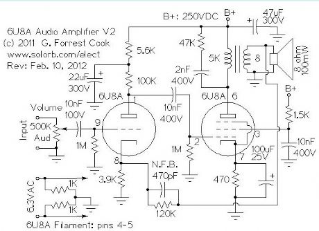
The line-level audio signal is sent through a 100K audio volume control and into the grid of the 6U8A triode section. The triode is wired as a standard class-A tube amplifier. The B+ line to the triode is isolated from the final amplifier's B+ through a 5.5K/22uF low pass filter, this prevents interstage feedback and oscillation.
The output of the triode amp is sent to the control grid of the 6U8A pentode section through a 10nF capacitor. The pentode is wired as a class-A amplifier with a transformer output. A negative feedback loop linearizes the amplifier's frequency response, this consists of a 120K resistor and 470pF capacitor from the speaker side of the output transformer to the cathode of the 6U8A triode. Feedback is kept to a fairly light level to preserve the amp's dynamics. The R/C network across the output transformer primary was adjusted for a flat frequency response. The pentode's screen grid is pulled up to the B+ voltage through a 1.5K current limiting resistor and AC-bypassed with a 10nF capacitor.
If a tone control is desired, it can be built onto the feedback loop, see my Squirrel Monkey amp project for an example of this type of tone control. If you build the amplfier and it oscillates, swap the output leads on the output transformer to correctly phase the feedback signal.
The power supply is not shown, this amp is designed to be an audio module that can be combined with other modules to build a radio or other audio devices. Any standard vacuum tube power supply should work here, it just needs to provide 6.3VAC for the filament and 250VDC for the B+ circuit. The amp should work fine with B+ values between 150VDC and 300VDC. Again, see my Squirrel Monkey amplifier for a power supply that will work with this amplifier.
(View)
View full Circuit Diagram | Comments | Reading(4055)
| Pages:19/250 1234567891011121314151617181920Under 20 |
Circuit Categories
power supply circuit
Amplifier Circuit
Basic Circuit
LED and Light Circuit
Sensor Circuit
Signal Processing
Electrical Equipment Circuit
Control Circuit
Remote Control Circuit
A/D-D/A Converter Circuit
Audio Circuit
Measuring and Test Circuit
Communication Circuit
Computer-Related Circuit
555 Circuit
Automotive Circuit
Repairing Circuit