
Amplifier Circuit
Index 39
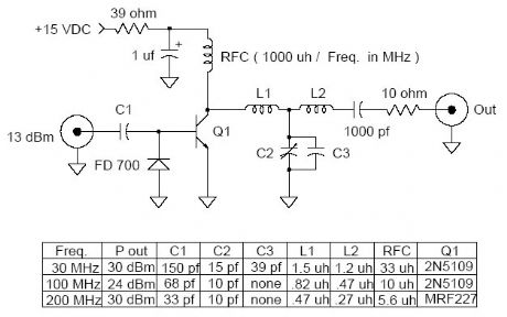
1 Watt Universal RF Amplifier
Published:2012/11/9 20:59:00 Author:muriel | Keyword: 1 Watt , Universal, RF Amplifier
View full Circuit Diagram | Comments | Reading(2073)
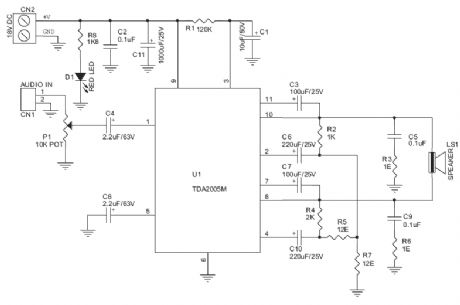
Homemade mini - amplifier and speaker circuit diagram
Published:2012/11/9 19:28:00 Author:Ecco | Keyword: mini - amplifier, speaker
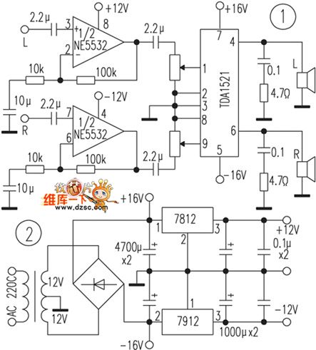
The amplifier part uses fidelity Manifold TDA1521, and its peripheral integrated circuit is extremely simple, and it has overheating, squelch, short circuit and other protection circuits, and it is suitable for homemade beginners. The first class uses the NE5532 for 10 times line amplifier. The coupling capacitor can use domestically CBB capacitors or tantalum capacitors. The previous level power can be gotten by 7815,7915 regulator, and the power transformer should use more than 30W. Bridge rectifier can use 3A full bridge. Amplifier part is shown in Figure 1, the power part of the circuit is shown in Figure 2.
(View)
View full Circuit Diagram | Comments | Reading(3035)
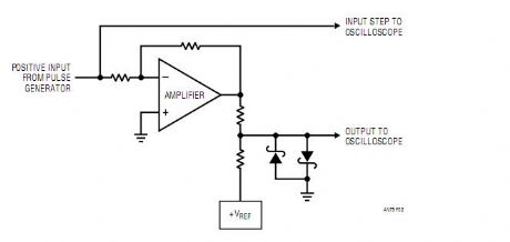
30 Nanosecond Settling Time Measurement for a Precision Wideband Amplifier
Published:2012/11/9 0:21:00 Author:muriel | Keyword: 30 Nanosecond, Settling Time, Precision Wideband Amplifier
View full Circuit Diagram | Comments | Reading(1070)
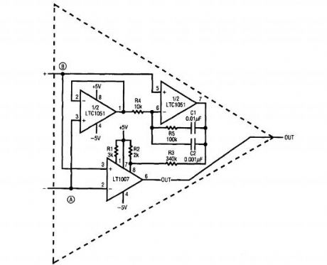
Ultra low noise op amp
Published:2012/11/9 0:16:00 Author:muriel | Keyword: Ultra, low noise, op amp
View full Circuit Diagram | Comments | Reading(1109)
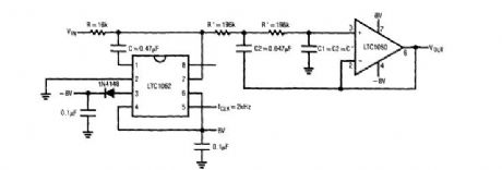
LTC1050 chopper op amp
Published:2012/11/9 0:15:00 Author:muriel | Keyword: LTC1050 , chopper op amp
View full Circuit Diagram | Comments | Reading(1764)
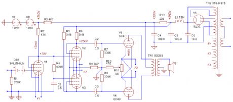
Last stage power amplifier circuit diagram
Published:2012/11/1 22:28:00 Author:Ecco | Keyword: Last stage, power amplifier
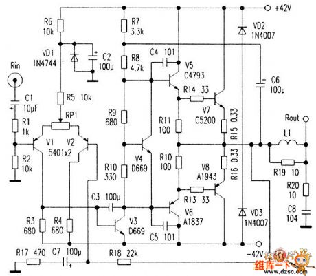
V1, V2 form a single-ended input, single-end output differential amplifier, V3 constitutes a voltage amplifier. In order to ensure that there is sufficient gain and distortion improvment, V4 is used for temperature compensation. V5, V6 are current push tubes which mainly provide the necessary current for the power amplifier tube to reduce the input impedance of the power amplifier tube. The high-power tube uses the recently popular ZSC5200/2SA1943 pairing tube. R18 is the negative feedback resistor, the closed-loop gain of the machine is determined by R18, R17, C6 is the bootstrap capacitor.
(View)
View full Circuit Diagram | Comments | Reading(2632)
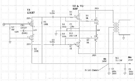
Push-Pull Class A Amp using type 5687 dual triodes
Published:2012/10/29 21:51:00 Author:muriel | Keyword: Push-Pull Class A Amp, 5687 dual triodes
View full Circuit Diagram | Comments | Reading(1526)
Push-Pull Class A 2A3 Stereo Amp
Published:2012/10/29 21:50:00 Author:muriel | Keyword: Push-Pull Class , A 2A3, Stereo Amp
View full Circuit Diagram | Comments | Reading(2197)
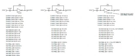
diode-connected MOSFET with buffer amplifier output
Published:2012/10/29 21:45:00 Author:muriel | Keyword: diode-connected MOSFET , buffer amplifier output

View full Circuit Diagram | Comments | Reading(1351)
CMOS Logic Inverter Amplifier
Published:2012/10/29 21:44:00 Author:muriel | Keyword: CMOS, Logic Inverter Amplifier
View full Circuit Diagram | Comments | Reading(1172)
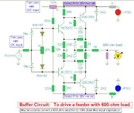
Buffer Amplifier circuit
Published:2012/10/29 21:42:00 Author:muriel | Keyword: Buffer Amplifier circuit
View full Circuit Diagram | Comments | Reading(1688)
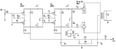
All-directly-Heated Pushpull Amp
Published:2012/10/29 21:41:00 Author:muriel | Keyword: All-directly-Heated, Pushpull Amp
View full Circuit Diagram | Comments | Reading(1067)
20-W Bridge Audio Amplifier
Published:2012/10/29 1:48:00 Author:muriel | Keyword: 20-W , Bridge Audio Amplifier
View full Circuit Diagram | Comments | Reading(1083)
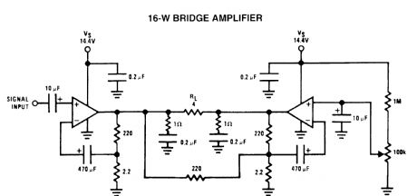
16-W bridge amplifier circuits
Published:2012/10/29 1:47:00 Author:muriel | Keyword: 16-W, bridge amplifier circuits
View full Circuit Diagram | Comments | Reading(1784)
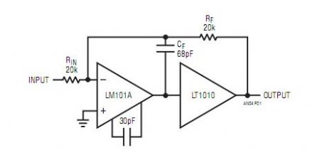
Practical LT1010 Based Boosted Op Amp
Published:2012/10/29 1:45:00 Author:muriel | Keyword: Practical LT1010, Based Boosted , Op Amp
View full Circuit Diagram | Comments | Reading(1221)
Low-noise ac amplifier has digital control of gain and bandwidth
Published:2012/10/29 0:54:00 Author:muriel | Keyword: Low-noise ac amplifier
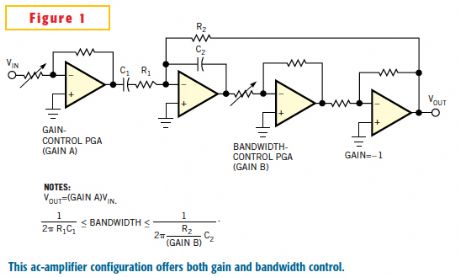
In low-noise analog circuits, a high-gain amplifier serves at the input to increase the SNR. The input signal level determines the input-stage gain; low-level signals require the highest gain. It is also standard practice in low-noise analog-signal processing to make the circuit's bandwidth as narrow as possible to pass only the useful input-signal spectrum. The optimum combination of an amplifier's gain and bandwidth is the goal of a low-noise design. In a data-acquisition system, digital control of gain and bandwidth provides dynamic adjustment to variations in input-signal level and spectrum. Figure 1 shows a simplified circuit for an ac amplifier with control of both gain and bandwidth. The amplifier's input is a PGA (programmable-gain amplifier) providing gain control (Gain A). Following the input PGA is a first-order highpass filter formed with capacitor C1 and input resistor R1 of an integrator circuit. Inside the integrator's feedback path, the gain of a second PGA (Gain B) multiplies the integrator's –3-dB frequency, thus providing bandwidth control. (View)
View full Circuit Diagram | Comments | Reading(1930)
Low Noise Microphone Preamplifier
Published:2012/10/29 0:53:00 Author:muriel | Keyword: Low Noise, Microphone Preamplifier
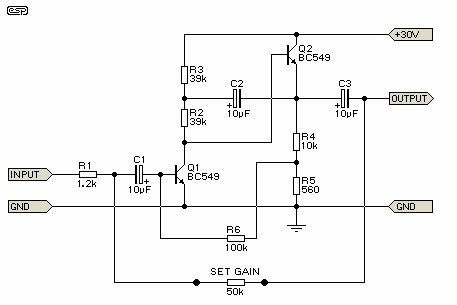
This is a design for a low noise microphone preamplifier, which is ideally suited to low impedance (600 Ohm nominal) microphones. One limitation is that it is not balanced, which is not a problem in a home recording environment, but will allow the mic lead (and case) to pick up noise with long cable runs or in a hostile environment.
As shown, it is not really suitable for professional work (although it has been used on stage in its unbalanced form with good results), but the addition of a 1:1 microphone transformer on the input will convert it into a balanced preamp with very high performance. In many cases, a transformer will actually outperform active balancing circuits, because there is (or should be) no ground reference. The shield of the balanced cable must be earthed of course, but in my experience with live music and studio work, less noise is picked up if the internal wiring is floating.
It is most regrettable that good mic transformers are rather hard to come by, and are expensive. If you happen to have a suitable one in your junk box, give it a try with this circuit - I doubt that you will be disappointed with the result. I have used this circuit in Front-of-House, foldback (monitor) and studio mixers, and managed to obtain excellent results - I still have a little 6 channel mixer (which I use only occasionally now) using this circuit, and have never been even slightly tempted to replace it with even the best of opamps (or Figure 3 for that matter). (View)
View full Circuit Diagram | Comments | Reading(4597)
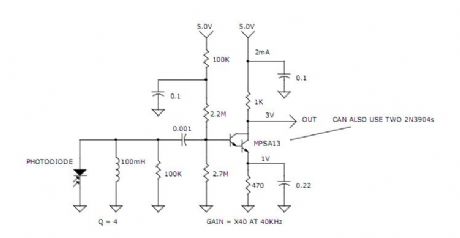
medium power 40kHz light receiver amp
Published:2012/10/29 0:52:00 Author:muriel | Keyword: medium power , 40kHz , light receiver amp
View full Circuit Diagram | Comments | Reading(874)
Low Noise Balanced Microphone Preamp
Published:2012/10/29 0:51:00 Author:muriel | Keyword: Low Noise, Balanced Microphone Preamp
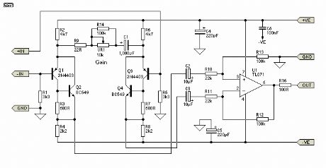
The input stage is configured for least noise and this has meant a non IC approach. There are some special ICs that can be used for mic pre-amps, they contain a circuit like this one except fabricated on one chip. Examples include the SSM2017 (now obsolete) or the replacement INA103 or similar.
Components should all be readily available except for the 10 k ohm pot for the gain control. This needs to be a reverse log taper - or else use a multi-position switch with 6 dB gain steps covering the 60 dB range of the circuit. Make sure it is make before break.
Editor's Note - Alternatively, a standard log pot can be used, but wired backwards . This will work fine if it is labelled Attenuation instead of Gain . As the pot is advanced clockwise, the gain is reduced (attenuation is increased). Maximum gain will therefore be applied when the pot is fully anti-clockwise. Note that this is not a problem that is specific to this circuit - all the IC mic preamps have exactly the same problem. (View)
View full Circuit Diagram | Comments | Reading(3463)
The gain or programming amplifier PCB circuit diagram
Published:2012/10/25 21:05:00 Author:Ecco | Keyword: gain , programming, amplifier , PCB
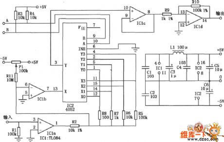
As shown in figure, the amplifier circuit can respectively provide 1, 10, 100, 1000 magnification factors under four kinds of logic level control, and each magnification bandwidth is greater than 30kHz, the entire circuit's current is less than 7mA under± 5V supply.
(View)
View full Circuit Diagram | Comments | Reading(1279)
| Pages:39/250 At 202122232425262728293031323334353637383940Under 20 |
Circuit Categories
power supply circuit
Amplifier Circuit
Basic Circuit
LED and Light Circuit
Sensor Circuit
Signal Processing
Electrical Equipment Circuit
Control Circuit
Remote Control Circuit
A/D-D/A Converter Circuit
Audio Circuit
Measuring and Test Circuit
Communication Circuit
Computer-Related Circuit
555 Circuit
Automotive Circuit
Repairing Circuit