
Index 130
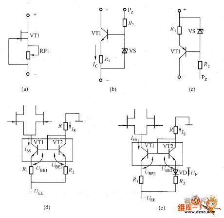
Basic constant current circuit diagram
Published:2011/8/7 6:27:00 Author:nelly | Keyword: constant current
View full Circuit Diagram | Comments | Reading(873)
The compare circuit diagram of LM324
Published:2011/8/7 8:36:00 Author:nelly | Keyword: compare

If you do not want to so much trouble, you can define the value of R2 at first. R1 uses the adjustable resistor to adjust the value of R1. At the point of V1, the multimeter is used to measure the voltage. When the voltage of V1 reaches the wanted threshold, the value of R1 will be defined. The threshold of the other voltage has the same principle.
(View)
View full Circuit Diagram | Comments | Reading(4392)
Current expansion circuit composed of μA741
Published:2011/8/4 21:25:00 Author:Rebekka | Keyword: Current expansion
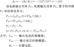
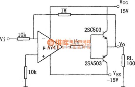
Usually the output current of the op amp is about 10 ~ 30mA. For the operation amplifier circuit is composed of the μA741, When the output current is greater than 10 ~ 35mA, its output voltage will appear limiting phenomenon, that means the output voltage will be a greater distortion. When you need a higher output current, you can use the geminate transistor formed by the 2SC503 and 2SA503. The so-called geminate transistor means that its input and output characteristics are almost identical to the transistor. When you use it, it should be strictly selected. It can not be used randomly assigned. The circuit output current can be up to 120mA, the magnification times of the voltage is show as above.
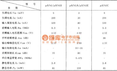
μA741 Electrical Characteristics table (VD = ± 15V; TA = 25 ℃). (View)
View full Circuit Diagram | Comments | Reading(1227)
High-performance quadrature sine wave type oscillator circuit
Published:2011/8/6 7:54:00 Author:nelly | Keyword: High-performance, quadrature, sine wave type, oscillator
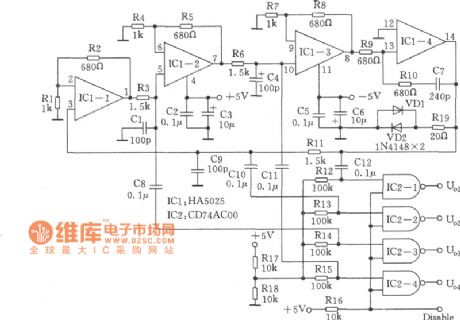
Many RC oscillators use the advanced circuits in the phase shift unit. They use the voltage feedback amplifier, and the gain of the voltage feedback amplifier will reduce sharply in the high frequency, and gain will stop, when it has not reached the high frequency. The difference of the voltage feedback amplifier phase characteristic is the reason. The high frequency IC HA5025, which contains four current feedback amplifiers, is used to make the RC oscillator, thus four quadrature sine waves will be formed, as shown in the picture. (View)
View full Circuit Diagram | Comments | Reading(2185)
Digital sine wave generator circuit
Published:2011/8/7 8:45:00 Author:nelly | Keyword: Digital, sine wave, generator
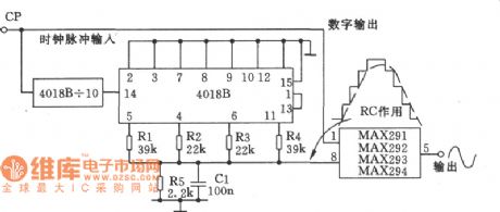
The picture shows the digital sine wave generator. It is composed of analog-digital converter (4018B) and a fixed filter (MAX29X). One part of the clock pulse, which inputs the CP, drives the filter MAX29X. The other part of the clock pulse is divided by the 10-digit counter (4018B), and then it is divided by the second counter. The output step wave will change to the smooth sine wave by R5 and C1, and then it is output by the filter. The output frequency of the circuit will change with the clock input, the relationship is fout=fin/l00。
(View)
View full Circuit Diagram | Comments | Reading(3530)
4kHz harmonic generator circuit
Published:2011/8/7 4:40:00 Author:nelly | Keyword: harmonic generator
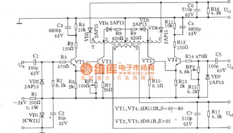
The harmonic generator has the differential type. Through the output transformer, the two rectangular pulses, which have half circle difference, are coupled by the symmetrical differential amplifier circuit. Thus the harmonic generator circuit can be achieved. It is simple, and easy to maintenance. It also has the low cost and saves the characteristics of symmetrical pulse. The performance can be closed to the magnetic saturation type. The 4 kHz harmonic generator is as shown in the picture. Its generating frequency is mainly controlled by the main oscillator. Odd and even harmonics can be used for the presetting, access and road base of the communication machine, and it also can be used for the carrier frequency and pilot frequency of the modulation.
(View)
View full Circuit Diagram | Comments | Reading(1281)
1024kHz and 4kHz sine wave output circuit
Published:2011/8/7 1:54:00 Author:nelly | Keyword: sine wave, output
This SJT circuit is the 1024kHz warming crystal oscillator. The principle of this circuit is as shown, because the output signal is low, the follow-up transistor VT1 is used to buffer and amplify. The base of VT1 offsets resistor R2, carrier resistor R3. Emitter resistor R4 is the negative feedback resistor, which is used to stabilize the DC working point of VT1. The zener diode VD1, VD2 and capacitor c1 form the regulator and filter circuit. The regulator and filter circuit is used to reduce crystal SJT’s influence caused by supply voltage.
(View)
View full Circuit Diagram | Comments | Reading(677)
12kHz signal generator circuit
Published:2011/8/6 22:21:00 Author:nelly | Keyword: signal generator
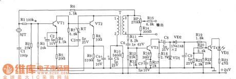
The 12kHz signal generator as shown is composed of crystal oscillator and alarm circuit. The output amplitude of the oscillator is stable, change <±0.26dB. Component selection: transistor VTl, VT3: 9014,65 ≤ β ≤ 115; VT2, VT4: 3DGl308, 60 ≤ β ≤ 85. Thermistor RT: RRWl-2 type. Quartz crystal SJT: BE42-12kHz. Transformer T applies the ferrite MXD-2000, and the magnetic core is GV36X22. Ll-2Φ0.17mm high strength wire, wound 27 turns, L3-4Φ0.17mm high strength wire, wound 37 turns. The LED VD3 can be any type. (View)
View full Circuit Diagram | Comments | Reading(657)
E-Insurance circuit diagram
Published:2011/8/4 20:30:00 Author:Rebekka | Keyword: E-Insurance
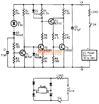
The circuitis suitable for the DC power supply overcurrent protection, such as a variety of battery-powered applications. If the load current exceeds a preset value, the insurance will disconnect the DC electronic load. When you reset the circuit, you just need to cut the power off. The circuit has two connection points (A, B tag), the load can be connected to either side. Load current flows through the transistor T4, resistor R10 and R11. A, B terminals' voltage and load current are proportional to the majority of the voltage distribution in the resistor. (View)
View full Circuit Diagram | Comments | Reading(674)
12kHz IF signal generator circuit
Published:2011/8/6 21:33:00 Author:nelly | Keyword: IF, signal generator
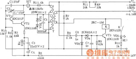
As shown in the picture, the circuit is composed of the IF oscillator and alarm circuit. It applies the variable feedback oscillator circuit, and the oscillator frequency is mainly determined by the quartz crystal. C1 and C2 can be used as the fine turning frequency. Oscillating pipe uses the composite pipe to improve the input impedance, and the stability of the magnitude is achieved by the VD1 and VD2 two-way regulation. Specifications: (1) Nominal frequency: 12kHz, and the frequency difference does not exceed ± 1Hz; (2) Frequency Accuracy: in the temperature range of 25±25℃, and ΔF does not exceed ± lHz; (3) U01 output level: -28dB/600Ω, deviation is less than ± 0.2dB;
(View)
View full Circuit Diagram | Comments | Reading(712)
450 audio signal generator circuit
Published:2011/8/6 8:27:00 Author:nelly | Keyword: audio signal, generator
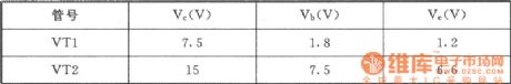
This oscillator is the signal source of the communication unit users. The working principle is as shown in the picture. It is composed of the VT1, VT2 and the related components. VTl uses the transformer T coupling to generate the oscillator signal, and the VT2 is the buffer amplifier of common collector circuit. T changer 1—4 winding form the frequency selective network. In order to prevent the magnetic saturation, T is connected to the collector of VT| by 1-2 tap, 5-6 of T is the feedback coil. Test: The pin of the every DC potential (reference value) is as shown in the table.
(View)
View full Circuit Diagram | Comments | Reading(962)
MIDI receiving circuit diagram
Published:2011/8/5 1:15:00 Author:Ecco | Keyword: MIDI
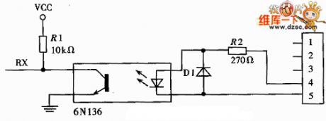
Transmission cable uses the shielded twisted pair cable, because the signal transmission uses current signal to replace voltage signal, it has strong anti-interference ability, although its rate is up to 31.5kbps, transmission distance can still reach 15m, which is further than the common the transmission distance of RS-232 interface. General MIDI receiver circuit is shown as below.
(View)
View full Circuit Diagram | Comments | Reading(648)
500Hz signal generator circuit
Published:2011/8/6 8:17:00 Author:nelly | Keyword: signal generator
2. Working principle is as shown in the picture.
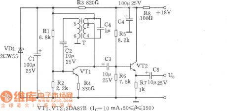
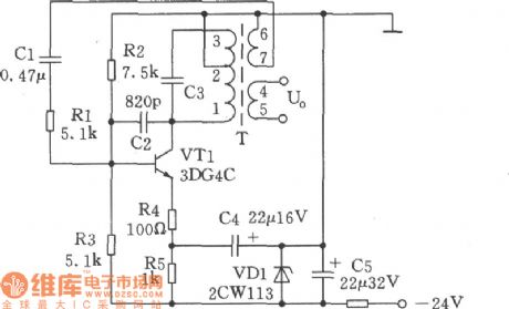
The 500Hz oscillator is composed of VTl, T, VDl, resistor, capacitors and so on. The oscillator frequency is decided by the parallel resonant frequency of C3 and L1-3. Resistor Rl is used to improve the input impedance of the transistor VTl, so the influence to the oscillator also can be reduced. R2, R3 are the DC bias resistors. R4 and R5 are the VTl emitter resistors, and R4 has the current negative feedback function. In order to adapt the change of supply voltage, the voltage of two ends should be regulated. Under normal circumstances, the output level of L4-5 is 0dB±2.6dB/600Ω, and the oscillation frequency is 500Hz.
(View)
View full Circuit Diagram | Comments | Reading(920)
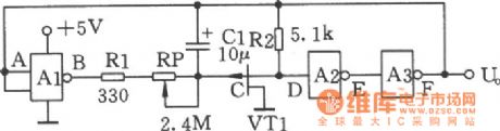
The simple pulse signal generator circuit composed of 4LS00, 74LS221
Published:2011/8/6 3:10:00 Author:nelly | Keyword: simple, pulse signal, generator
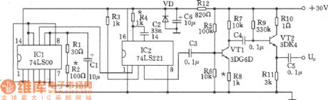
The simple pulse signal generator circuit is as shown. This signal generator mainly uses two TTL ICs (74LS00 and 74LS221) to produce the pulse signal of τ=4μs; Therefore, it uses fewer components, and the maintenance and adjustment will be very simple.
(View)
View full Circuit Diagram | Comments | Reading(1150)
Double pulse generator (HEF4538) circuit
Published:2011/8/6 2:24:00 Author:nelly | Keyword: Double, pulse generator
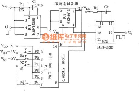
The double pulse generator (HEF4538) circuit is as shown: (View)
View full Circuit Diagram | Comments | Reading(2691)
Ultra-low frequency pulse generator circuit
Published:2011/8/6 2:50:00 Author:nelly | Keyword: Ultra-low, frequency pulse, generator
The figure shows the Ultra-low frequency pulse generator. The pulse generated by this device has 0.15 to 50s width. (View)
View full Circuit Diagram | Comments | Reading(1157)
Carat poured signal generator circuit
Published:2011/8/6 8:04:00 Author:nelly | Keyword: Carat poured, signal, generator
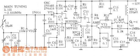
The Carat poured signal generator circuit is as shown. VTl is the variable LC oscillator formed by the typical high-stable Carat poured circuit. The capacity of the capacitance C4 and C5 is very large, and capacitance C4 and C5 can decide the feedback coefficient. The short flutter rate of drift, which is caused by the capacitance change, can be reduced by this carat poured signal generator.
(View)
View full Circuit Diagram | Comments | Reading(650)
Linear CMOS oscillator circuit
Published:2011/8/6 3:03:00 Author:nelly | Keyword: Linear, CMOS, oscillator
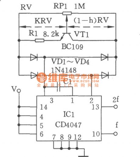
Figure shows the linear CMOS oscillator circuit. With the potentiometer RPl , the frequency of the CD4047 CMOS can be adjusted in the range of 1:100. When the transistor, which can be used as the variable resistor, is added, the adjustment circuit, which can have the linear relationship with the frequency, can be formed. The emitting resistor RI of VTI can set the current of IC with the variable base voltage. the electric bridge, which is formed by the diode VDl ~ VD4,is used to ensure the symmetry work both in negative and positive cycle.
(View)
View full Circuit Diagram | Comments | Reading(2000)
Frequency modulation (FM) waveform generator circuit
Published:2011/8/6 2:22:00 Author:nelly | Keyword: Frequency modulation, waveform generator
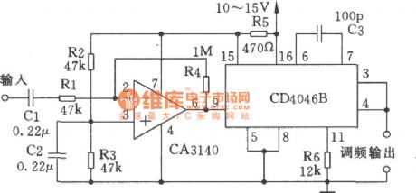
The figure shows the frequency modulation waveform generator circuit which can generate 220 kHz frequency. The regulator, which is inside the CD4068, can provide the stable supply voltage for the op-amp CA3140. The rated voltage is 5.4V, and R5 is the limiting resistor of regulator. (View)
View full Circuit Diagram | Comments | Reading(1728)
Single-junction transistor sine wave oscillator circuit
Published:2011/8/7 1:30:00 Author:nelly | Keyword: Single-junction, transistor, sine wave, oscillator
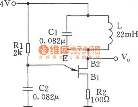
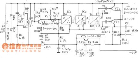
The single-junction transistor is always used in the sawtooth generator and pulse generator, and it also can form the simple sine wave generation circuit. As an oscillator circuit of the discrete component, it uses fewest components. As the figure shown, compared with the simple single-junction tube remittent oscillator circuit, this circuit adds a LC tuned circuit at the second base. By the excitation of the single-junction tube current pulse, the tuned circuit generates sine wave oscillation. Tuned resistor R1 can control the size of current pulse and have the sine wave at B2.
(View)
View full Circuit Diagram | Comments | Reading(3956)
| Pages:130/471 At 20121122123124125126127128129130131132133134135136137138139140Under 20 |
Circuit Categories
power supply circuit
Amplifier Circuit
Basic Circuit
LED and Light Circuit
Sensor Circuit
Signal Processing
Electrical Equipment Circuit
Control Circuit
Remote Control Circuit
A/D-D/A Converter Circuit
Audio Circuit
Measuring and Test Circuit
Communication Circuit
Computer-Related Circuit
555 Circuit
Automotive Circuit
Repairing Circuit