
Basic Circuit
Index 28
Controlling Single Coil Switch Machines 3
Published:2013/6/18 21:38:00 Author:muriel | Keyword: Single Coil, Switch Machines
View full Circuit Diagram | Comments | Reading(621)
Controlling Single Coil Switch Machines 2
Published:2013/6/18 21:37:00 Author:muriel | Keyword: Single Coil, Switch Machines
View full Circuit Diagram | Comments | Reading(642)
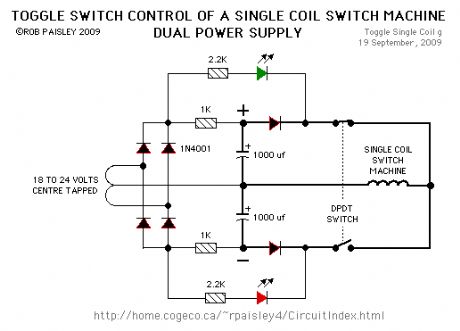
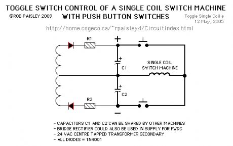
Controlling Single Coil Switch Machines
Published:2013/6/18 21:11:00 Author:muriel | Keyword: Controlling , Single Coil, Switch Machines
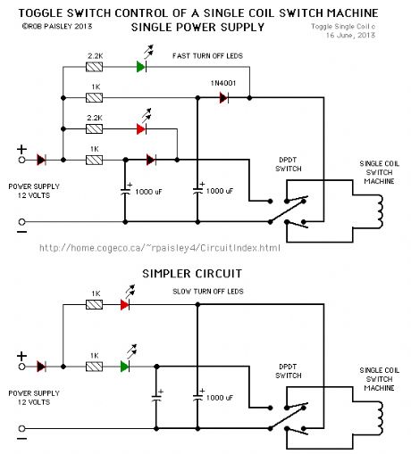
This circuit allow an ON-ON type DPDT toggle switch to control a single coil switch machine motor such as those made by Kato®. The handle of switch can then be used to indicate the route selected. The circuit is also able to control LEDs that could be used to indicate the selected route.
The main disadvantage of this circuit is the cost of two large electrolytic capacitors per switch machine. This could be offset by bulk or surplus purchases of the capacitors.
The size of the capacitors depends on the power needed to throw the turnout and the supply voltage. The value of the charging resistors depends on how quickly the turnout will be returned to its last position. A resistance of 1000 ohms would be a practical value in most cases.
NOTE:Although these circuits are show using DPDT toggle switches, 3 and 4 pole switches could also be used to control frog polarity or signals with the extra poles.
The resistors should have a 1/2 watt or greater power rating. The capacitors can be between 1,000 and 2,200 microfarads and should have a 35 volt or higher rating.
(View)
View full Circuit Diagram | Comments | Reading(1003)
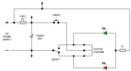
Set Signal / Then Throw
Published:2013/6/18 21:10:00 Author:muriel | Keyword: Set Signal , Then Throw
View full Circuit Diagram | Comments | Reading(636)
Fast Recovery Circuit
Published:2013/6/18 21:10:00 Author:muriel | Keyword: Fast Recovery Circuit
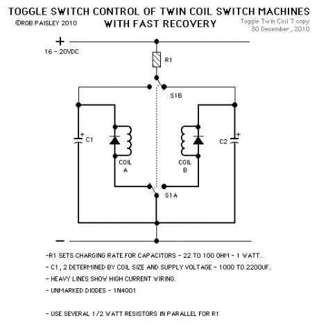
View full Circuit Diagram | Comments | Reading(591)
Separate Coils With Separate LED Control
Published:2013/6/18 21:09:00 Author:muriel | Keyword: Separate Coils , Separate LED Control

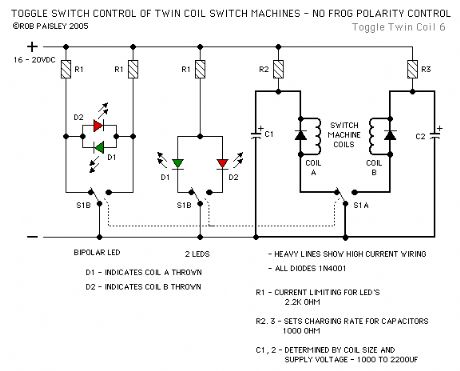
View full Circuit Diagram | Comments | Reading(770)
Separate Coils With Transistor Control
Published:2013/6/18 21:08:00 Author:muriel | Keyword: Separate Coils, Transistor Control
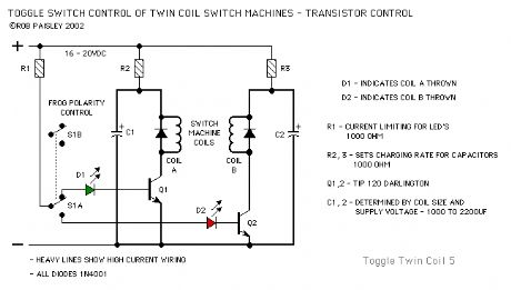
View full Circuit Diagram | Comments | Reading(752)
Separate Coils With Frog Polarity Control
Published:2013/6/18 21:08:00 Author:muriel | Keyword: Separate Coils , Frog Polarity Control
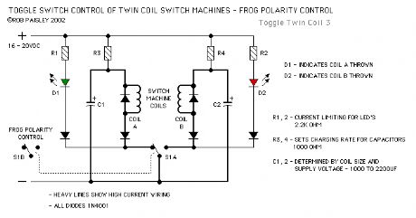
View full Circuit Diagram | Comments | Reading(791)
For Switch Machines With A Fixed - Coil Common Connection
Published:2013/6/18 21:07:00 Author:muriel | Keyword: Switch Machines, Coil Common Connection
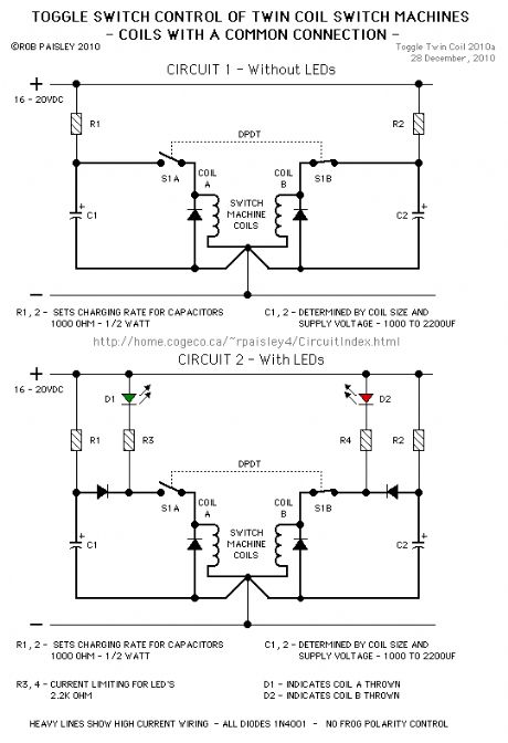
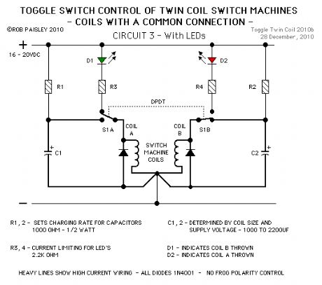
The first three circuits are for use with switch machines that have an unbreakable connection between the two coils such as those made by Atlas®. These circuits can also be used with twin coil switch machines that have separate coils.
The next circuit is a variation on the circuits above. This circuit makes use of all the poles on the DPDT toggle switch. (View)
View full Circuit Diagram | Comments | Reading(704)
Stepdown Transformers
Published:2013/6/18 21:04:00 Author:muriel | Keyword: Stepdown Transformers
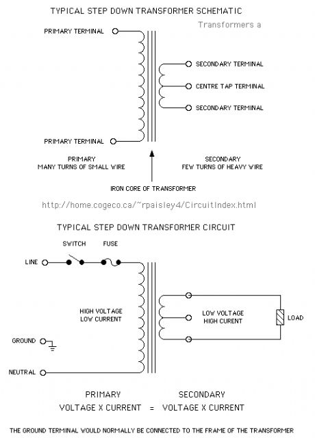
The step down transformer is the interface between the household Alternating Current system and the electronics that run your model railroad. The main purpose of the transformer is to reduce the relatively high voltage of the house to a safer and more practical voltage.
There is also a secondary function that often goes un-noticed which is to provide electrical isolation between the household supply and the layout. This, in a properly constructed circuit, prevents the layout from being exposed to a dangerously high voltage if there is a fault on the primary side of the circuit.
This isolation also separates the power supplies of each subsystem on the layout from the others. For example; On layouts with multiple DC throttles, each throttle is isolated from the others by its transformer. This allows common rail block wiring without causing a short circuit.
The capacities of transformers are often given as a Volt/Ampere rating. This is the secondary voltage multiplied by the secondary current at full load and is roughly equivalent to a wattage rating but makes allowances for the peculiarities of alternating current. These allowances are not relevant to this page however.
The secondaries of many transformers designed for low voltage applications are simply rated as secondary volts at full load amps.
Note: The secondary voltage of a transformer is often significantly higher when there is no load than at full load. This is largely dependant on the the design of the transformer itself and is usually not a factor in model railroad circuits. However, in many low power and cheaply constructed transformers that are used in consumer electronics this voltage drop can be significant and must be taken into account when good regulation is needed.
Transformers are generally, very efficient devices and no allowance is usually required for the small amount of heat that they may generate. It is good practice however to provide space around the transformer for air circulation and ventilation for enclosures.
Power supply transformers should always be protected by a fuse on the primary side of the circuit. If a transformer supplies multiple loads, all loads should be be protected by individual fuses.
(View)
View full Circuit Diagram | Comments | Reading(987)
Bipolar Transistors
Published:2013/6/18 21:02:00 Author:muriel | Keyword: Bipolar Transistors
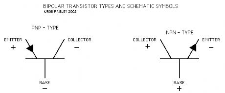
Bipolar transistors used in model railroad electronics come in two baseic types, NPN and PNP, and are used in two basic ways, switching and regulating. These transistors are available in a wide variety of voltage and current ratings.
(View)
View full Circuit Diagram | Comments | Reading(903)
Special Diode Types
Published:2013/6/18 21:02:00 Author:muriel | Keyword: Special Diode Types
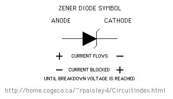
Three special types of diodes the model railroader is likely to encounter are the Small Signal diode, Schottky diode and Zener diode. A brief description and some uses of each follows.
Small Signal Diodes such a the 1N914 and 1N4148 are low voltage and current diodes but are very fast which makes then ideal for use with very high frequency circuits. These diodes are used in timing and pulse generation circuits.
Schottky Diodes such as the 1N5817 and 1N5820 are low voltage diodes but can handle currents of 1 amp and 3 amps respectively. Schottky diodes are fast and are used in DCC systems where high frequency operation is required.
Schottky diodes also have a lower forward voltage drop than silicon diodes which makes the useful in low voltage circuits.
Zener Diodes are normally used for voltage regulation and are available in a large range of breakdown voltage and device power ratings. The use of this type of diode is not as common now but may still be encountered in older circuit designs. (View)
View full Circuit Diagram | Comments | Reading(1468)
Bridge Rectifiers
Published:2013/6/18 21:01:00 Author:muriel | Keyword: Bridge Rectifiers
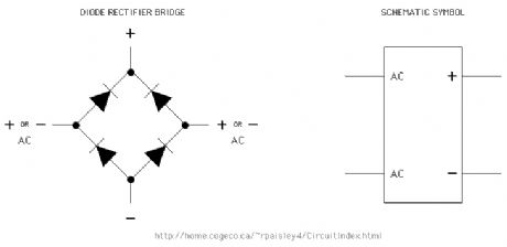
A common use of diodes is a rectifier bridge. A bridge is four diodes configured so that the output always has the same polarity regardless of the polarity of the input. Rectifier bridges are most often used to convert alternating current into full-wave direct current for power supplies and throttles.
Bridges can be made from four separate diodes or the diodes can be in one package. Bridge rectifiers are available in a wide variety of voltage and current ratings. (View)
View full Circuit Diagram | Comments | Reading(1880)
Diodes and Rectifiers
Published:2013/6/18 21:01:00 Author:muriel | Keyword: Diodes, Rectifiers
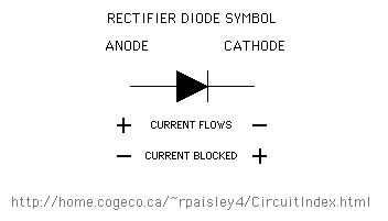
The primary function of diodes in model railroading is to allow the flow of current in one direction only. This is generally referred to as rectification.
Diodes have many uses such as to convert an alternating current to a direct current for power supplies and throttles and to route current in matrix circuits for switch machine controls. (View)
View full Circuit Diagram | Comments | Reading(725)
Really Basic Electricity
Published:2013/6/18 21:00:00 Author:muriel | Keyword: Really Basic Electricity
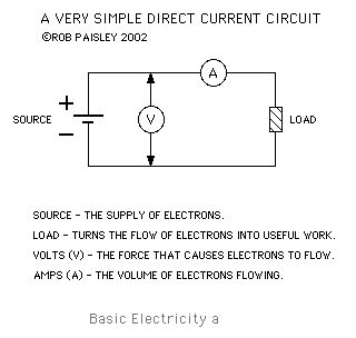
This page provides some really basic information on Direct Current electricity. It might be called Theory but will not be very in depth. The diagrams will be basic and the explanations will brief and to the point.
For the purposes of the Basic Electronics pages at this site it will be assumed that current flow is from the positive to the negative.Every circuit must contain the following elements; A Source of Electrons and a Load. These elements are able to produce useful work from the circuit and can be combined in an infinite number of ways to form any circuit.
SOURCE OF ELECTRONS The source of electrons in the circuit can be any of a wide range of devices. These include batteries, photovoltaic cells and thermocouples. The most usual source of electrons in model railroad circuits is the secondary of a stepdown transformer.
LOAD The load in the circuit coverts the flow of electrons into usable work. The work can include the production of light from light emitting diodes or the creation of a magnetic field in a motor or switch machine.
To provide a way of determining the work done by a circuit the energy in the circuit can be expressed using the following perameters.
VOLTS Is the force that causes the electrons to flow through a circuit. The greater the force, the higher the number of electrons that can be forced through a given circuit.
AMPS Is the rate of electron flow in the circuit. The greater the rate of electrons flowing the greater the work that will be done.
RESISTANCE Is the opposition to the flow of electrons in the circuit. The greater the resistance, the lower the rate of electron (Amps) flow in a circuit for a given voltage.
(View)
View full Circuit Diagram | Comments | Reading(954)
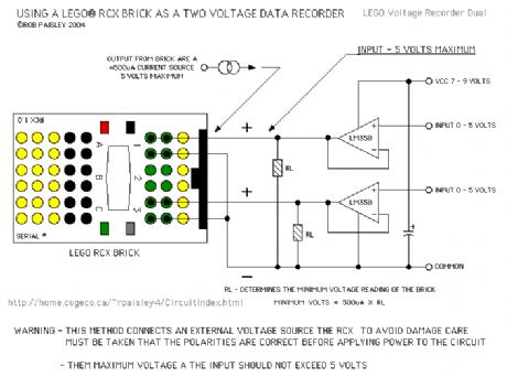
Dual Voltage Recorder Input Circuits
Published:2013/6/18 20:56:00 Author:muriel | Keyword: Dual Voltage , Recorder, Input Circuits
View full Circuit Diagram | Comments | Reading(631)
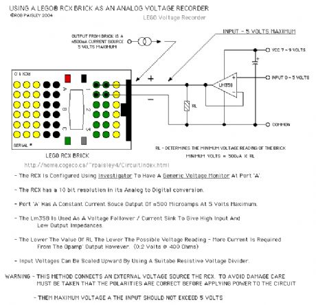
Basic Voltage Recorder Input Circuit
Published:2013/6/18 20:55:00 Author:muriel | Keyword: Basic Voltage , Recorder, Input Circuit
View full Circuit Diagram | Comments | Reading(582)
4 Lane - Automatic Reset - Race Scorer
Published:2013/6/18 20:52:00 Author:muriel | Keyword: 4 Lane, Automatic Reset, Race Scorer
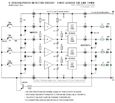
The next circuit will score 4 lanes and has automatic reset. The schematic shows four lanes but two, three of two sets of two lanes could be scored.
The variable 500K resistors shown in the first two circuits could be replaced by a fixed 470K resistor.
(View)
View full Circuit Diagram | Comments | Reading(722)
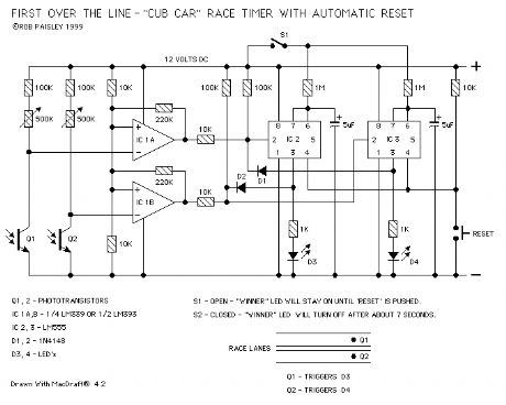
Automatic Reset - Race Scorer
Published:2013/6/18 20:52:00 Author:muriel | Keyword: Automatic Reset , Race Scorer
View full Circuit Diagram | Comments | Reading(625)
Basic Race Scorer
Published:2013/6/18 20:51:00 Author:muriel | Keyword: Basic Race Scorer
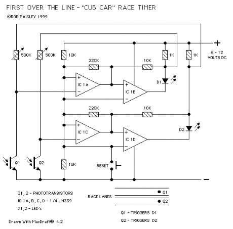
View full Circuit Diagram | Comments | Reading(634)
| Pages:28/471 At 202122232425262728293031323334353637383940Under 20 |
Circuit Categories
power supply circuit
Amplifier Circuit
Basic Circuit
LED and Light Circuit
Sensor Circuit
Signal Processing
Electrical Equipment Circuit
Control Circuit
Remote Control Circuit
A/D-D/A Converter Circuit
Audio Circuit
Measuring and Test Circuit
Communication Circuit
Computer-Related Circuit
555 Circuit
Automotive Circuit
Repairing Circuit