
Motor Control
Index
DC motor start circuit controlled by counter electromotive force
Published:2012/9/17 1:39:00 Author:Ecco | Keyword: DC motor start , counter electromotive force
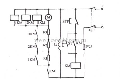
When breaker QF is closed, pressing the start button ST will make DC contactor KM pull in, the motor M connected to R1 , R2, R3 in series is started. With the speed increaseing, the counter electromotive force increases, the voltage at both ends of the motor M is increased gradually, so that 1KM, 2KM, 3KM operate in an order, the main contacts will sequentially shorting connect R1, R2, R3, and finally the motor M is put into full pressure operation. 1KM, 2KM, 3KM are DC contactors, the pull-in coil's rated voltage must meet U1KM < U2KM < U3KM.
(View)
View full Circuit Diagram | Comments | Reading(1501)
Ed Gray Motor Generator
Published:2012/9/16 21:56:00 Author:Ecco | Keyword: Ed Gray, Motor Generator
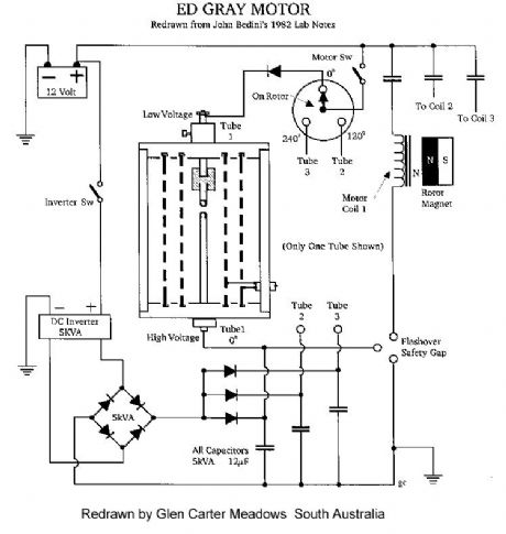
This type of design can produce a very high amperage current for a faction a second that can used to do some useful work if properly harnessed. The switching device could be a rotating spark gap as used by Nikola Tesla or some high speed electronic device, it is my belief that only glass tubes such as diodes or triode valves are really good at this and not transistors as they cannot handle the high voltage and high current produced in these devices without burning themselves out. (View)
View full Circuit Diagram | Comments | Reading(3526)
Free energy magnet motor
Published:2012/9/16 21:44:00 Author:Ecco | Keyword: Free energy , magnet motor
This invention relates to a method of producing useful energy with magnets as the driving force and represents an important improvement over known constructions and it is one which is simpler to construct, can be made to be self starting, is easier to adjust, and is less likely to get out of adjustment. The present construction is also relatively easy to control, is relatively stable and produces an amazing amount of output energy considering the source of driving energy that is used. (View)
View full Circuit Diagram | Comments | Reading(6834)
Medium Power 12v Brush Motor Speed Controller July 13, 2008
Published:2012/9/9 20:37:00 Author:Ecco | Keyword: Medium Power, 12v, Brush Motor, Speed Controller
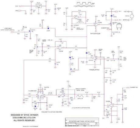
In many applications, you would like to hold the speed of a motor constant, even as variations in the power supply voltage or mechanical load try to change its speed. In other applications, the average current to the motor needs to be limited, so the initial in-rush current when starting the motor is not too high. Also in some applications you would like to allow the motor to be in locked in a stall condition, without doing harm to the motor or the drive circuit. These two features can often be combined in a single control circuit.
Source: discovercircuits (View)
View full Circuit Diagram | Comments | Reading(1071)
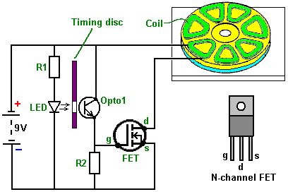
SOLAR POWERED PUMP MOTOR CONTROLLER
Published:2012/9/9 20:35:00 Author:Ecco | Keyword: SOLAR, POWERED , PUMP , MOTOR CONTROLLER
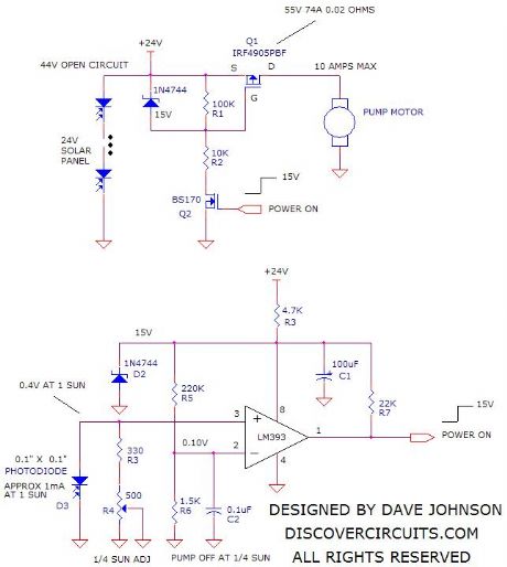
A Discover Circuits visitor had a problem. He needed a simple on/off controller for his solar powered water pump. His system used two 12v 50 watt solar panels wired in series. The power from the solar panels drove a submerged water pump. However, during overcast skies the pump motor did not operate properly due to the lack of power from the panel. He wanted a circuit which would turn off power to the motor during low sun conditions. The circuit below performs this function. A small 0.1? x 0.1? photodiode monitors the sunlight intensity. The current from the diode is proportional to sunlight intensity. An adjustable load resistor across the diode converts the current into a voltage and feeds the to a voltage comparator circuit. The output of the comparator drives a small n-channel MOSFET, which in turn drives a high current p-channel MOSFET, controlling power to the pump motor. When the sunlight is less than one fourth of full intensity, power to the motor is turned off.
Source: discovercircuits (View)
View full Circuit Diagram | Comments | Reading(2168)
The manual series resistor to start three-phase motor circuit
Published:2012/9/6 22:32:00 Author:Ecco | Keyword: manual series resistor , start , three-phase motor
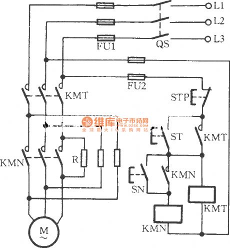
Operation method: you can click the start button ST, and AC contactor KMT will pull in, then the motor M connected to the startup resistor R in series will start. Until the motor speed is up to 70% of rated speed, and then clicking the run button SN again, KMN pulls in, and its main contact makes R be shorted connected and provides rated voltage for motor M, then the motor will enter the rated operating status.
(View)
View full Circuit Diagram | Comments | Reading(1256)
555 Timer Forms Simple PWM Motor Controller
Published:2012/9/5 20:35:00 Author:Ecco | Keyword: 555 , Timer Forms , Simple , PWM , Motor Controller
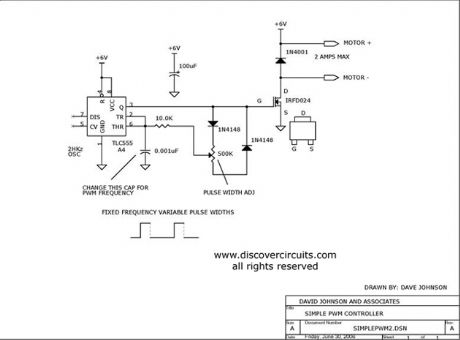
Using a CMOS version of the 555 timer, this circuit can be used to control the speed of a motor by adjusting the duty cycle of the pulses sent to the motor.
Source: discovercircuits
(View)
View full Circuit Diagram | Comments | Reading(4)
incandescent light life extension switch circuit
Published:2011/9/12 22:02:00 Author:John | Keyword: incandescent light, extension switch
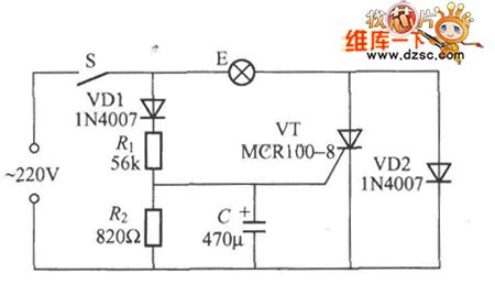
Incandescent light’s filament is with large thermal resistance and very small cold resistance. So at the moment of opening light, the impact current flowing through the filament is very large. It can be very easy to make the filament burn within damages. Life extension’s switch can be a good solution to this problem, just as shown in the figure.It can effectively extend lamp’s life greatly. When switch S is connected, the voltage across the capacitor can not change suddenly and the voltage across C is zero. The thyristor VT deadlines without triggering voltage. At this moment, the current flowing through the bulb E is the half-wave current rectified by VD2. The light bulb is pre-heated with darkness and the inrush current is very small.
(View)
View full Circuit Diagram | Comments | Reading(1567)
Double contact-plate resistance bridge touch switch circuit diagram
Published:2011/9/9 8:00:00 Author:Vicky | Keyword: double contact-plate, resistance bridge touch switch
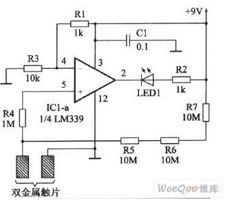

Resistance bridge touch switch in the picture 1 is composed of LM339. LM339 is a a quad voltage comparator (with 4 identical voltage comparator inside). The circuit only takes use of one of the four. Work voltage range reaches 2-32V. When hands are very close to the double metal plate but not touch them, pin2 of LM339 outputs low level signal, which makes the luminous diode LED1 conducted and lightened.
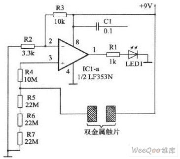
The difference of the resistance bridge touch switch in the picture 2 from picture 1 lies in that it adopts calculating amplifier LF353N instead of voltage comparator. (View)
View full Circuit Diagram | Comments | Reading(2292)
Bi-directional speed-adjusting motor driver circuit diagram
Published:2011/9/7 9:27:00 Author:Vicky | Keyword: bi-directional, speed-adjusting, motor driver circuit
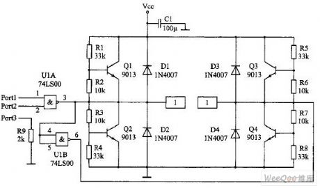
Output and level conversion
Output signal line is introduced by Port. Pin Port1 is the input end of motor direction signal, pin port2 is the PWN signal input end, and pin port3 is the grounding line. Attention that pin port3 is grounded and connected with a 2kΩ resistance. When the driver panel and monolithic provides power respectively, the resistance can provide the backflow passageway for signal circuit. When the driver and monolithic together use a same group of power, the resistance can prevent high current from flowing to the monolithic mainboard ground wire along the line which will lead to interference. Or, it is equivalent to separate the ground wire of the friver panel and the ground wire of monolithic, and to realize “one-point earth fault”. Capacitance C1 prevents the voltage from going down suddenly which is caused by the sudden start-up of the motor. (View)
View full Circuit Diagram | Comments | Reading(1325)
dual five-gear electronic switch controller circuit with CD4015,NE555
Published:2011/8/25 20:16:00 Author:chopper | Keyword: dual five-gear, electronic, switch controller
View full Circuit Diagram | Comments | Reading(6510)
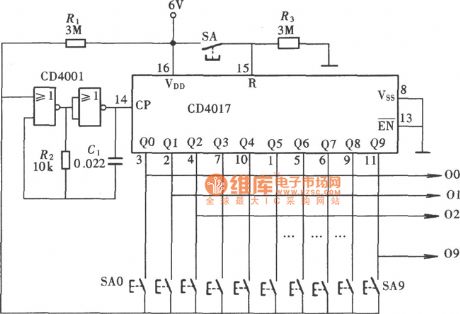
Ten-gear interlock switch controller circuit with CD4017,CD4001
Published:2011/8/25 20:12:00 Author:chopper | Keyword: Ten-gear, interlock switch, controller circuit
View full Circuit Diagram | Comments | Reading(3530)
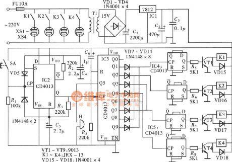
Home theater system power control switch CD4013,CD4017 circuit
Published:2011/8/25 20:13:00 Author:chopper | Keyword: Home theater, power, control switch
View full Circuit Diagram | Comments | Reading(5021)
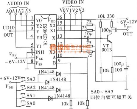
four-channel A/V convertion circuit(CD4052)
Published:2011/7/24 2:36:00 Author:chopper | Keyword: four-channel, A/V, convertion circuit
View full Circuit Diagram | Comments | Reading(11495)
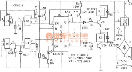
ten-gear interlock switch(CD4011,LM1812) circuit with audible and visual indication
Published:2011/7/23 2:25:00 Author:chopper | Keyword: ten-gear, interlock switch, audible and visual indication
View full Circuit Diagram | Comments | Reading(1650)
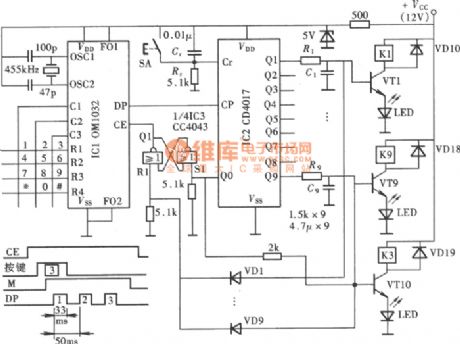
piano key type electronic switch OM1032,CD4043,CD4017 circuit
Published:2011/8/25 20:13:00 Author:chopper | Keyword: piano key, electronic switch
View full Circuit Diagram | Comments | Reading(3347)
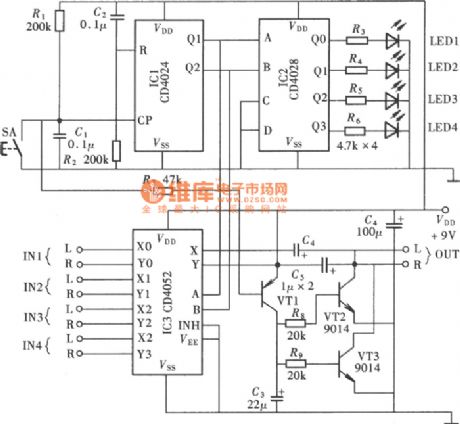
quadruple sound source input switching CD4024,CD4052 circuit
Published:2011/8/25 20:13:00 Author:chopper | Keyword: quadruple, sound source, input switching
View full Circuit Diagram | Comments | Reading(8881)
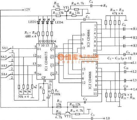
four-way electronic change-over switch circuit with CD40157,CD4066
Published:2011/7/22 3:22:00 Author:chopper | Keyword: four-way, electronic, change-over switch
View full Circuit Diagram | Comments | Reading(8229)
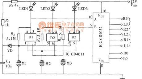
touch type three-way audio source change-over switch circuit with CD4052,CD4011
Published:2011/7/22 3:30:00 Author:chopper | Keyword: touch type, three-way, audio source, change-over switch
View full Circuit Diagram | Comments | Reading(6873)
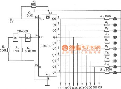
touch type ten-gear interlock switch controller circuit with CD4069,CD4017
Published:2011/7/22 3:09:00 Author:chopper | Keyword: touch type, ten-gear, interlock switch, controller circuit

View full Circuit Diagram | Comments | Reading(1376)
| Pages:1/6 123456 |
Circuit Categories
power supply circuit
Amplifier Circuit
Basic Circuit
LED and Light Circuit
Sensor Circuit
Signal Processing
Electrical Equipment Circuit
Control Circuit
Remote Control Circuit
A/D-D/A Converter Circuit
Audio Circuit
Measuring and Test Circuit
Communication Circuit
Computer-Related Circuit
555 Circuit
Automotive Circuit
Repairing Circuit