
Motor Control
Index 5
Stepper Motor Control Experimental Circuit
Published:2011/5/17 5:46:00 Author:Robert | Keyword: Stepper Moto, Control, Experimental
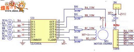
Learning the working principle and controlling methods of stopper motor and mastering some simple circuit-control and basic motor knowledge.
The Stepper Motor Control Experimental Circuit is shown below.
(View)
View full Circuit Diagram | Comments | Reading(1083)
Low Power AC/DC General Motor Thyristor Control Circuit
Published:2011/5/18 19:32:00 Author:Robert | Keyword: Low Power, AC/DC, General, Motor, Thyristor, Control
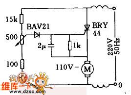
This circuit is used in the case of AC/DC general series wound motor stepless speed variation. Armature winding is in series with field winding through the thyristor. By the single-phase half-wave phase-shifting commutating control method, the thyristor's control angle could be changed by adjusting the 500ω potentiometer. So it can make the rotate speed be stepless adjusted from zero to the maximum value. This circuit is widely used in small household appliances such as blenders, sewing machines, hand drills and woodworking machinery.
(View)
View full Circuit Diagram | Comments | Reading(3735)
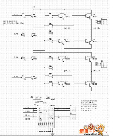
DC Motor Driving Circuit
Published:2011/5/18 10:03:00 Author:Robert | Keyword: DC Motor, Driving
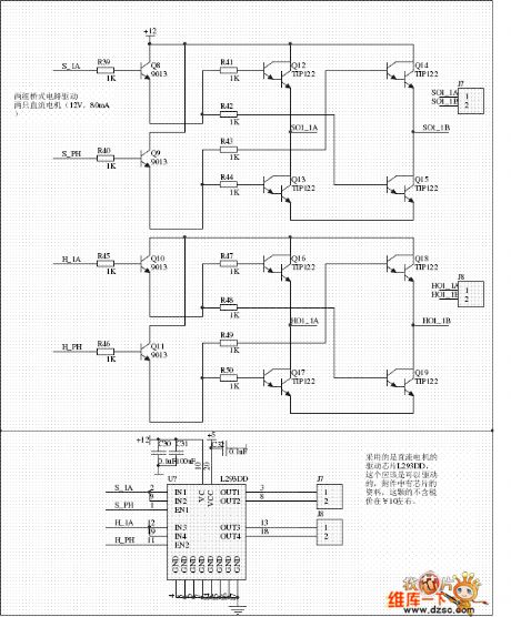
The DC Motor Driving Circuit is shown below.
These are two DC motor driving circuit, one is driven by electric bridge while the other is driven by integrated circuit L293DD, which is used to drive two DC motor (12V, 80mA). On the other hand, for L293DD input port,maybe it can make the IN1, IN2 (IN3, IN4) connected toghter separately and controlled by a MCU port.
(View)
View full Circuit Diagram | Comments | Reading(1636)
Stepper Motor General Driving Circuit
Published:2011/5/18 7:17:00 Author:Robert | Keyword: Stepper Motor, General, Driving
The Stepper Motor General Driving Circuit is shown below.
The integrated system uses small type stepper motor, which is not highly required on voltage and current. Tointroduce the application principle, this circuit uses the simplest driving circuit which aiming at verifying the use of stepper motor. When using in normal industrial control it needs to improve from this base model. General driving circuit can shown in picture as follow.
(View)
View full Circuit Diagram | Comments | Reading(588)
12V DC Motor Driving Circuit
Published:2011/5/11 7:43:00 Author:Robert | Keyword: 12V, DC Motor, Driving
The 12V DC Motor Driving Circuit is shown below.
(View)
View full Circuit Diagram | Comments | Reading(745)
DC Electric Motor Principle Model Circuit
Published:2011/5/11 2:55:00 Author:Robert | Keyword: DC, Electric Motor, Principle Model

To make the armature get a changeless direction electromagnetic torque, the key is: how to change the current's direction which flowing in the coil in time when the coil side is in differential magnetic polarity, which means the process of so-called direction commutation . So it must add a device called commutator. The commutator can coordinate with electric brush to guarantee that the coil side current in every polarity has always the same direction, which could make the electric motor to rotate continuously. Thisis the working principle of DC electric motor.
(View)
View full Circuit Diagram | Comments | Reading(1425)
DC Motor Control Circuit
Published:2011/5/11 7:42:00 Author:Robert | Keyword: DC, Motor, Control
Aboutthe DC motor control problem, This circuit is hoped to help those people who have the actual needs. This circuit's corotation, rollback, slowing and stopping functions can be controlled by the connected MCU.
(View)
View full Circuit Diagram | Comments | Reading(2147)
Straw And Feed Muller Control Circuit
Published:2011/5/6 3:07:00 Author:Robert | Keyword: Straw, Feed, Muller
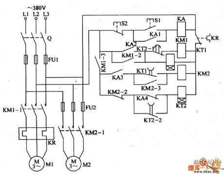
For the straw feed muller used in the countryside to process the corn, straw and grass and other animal feeding stuffs, some people use two electric motor (feeding motor and cropping motor) as the power to complete the crushing job for straw and feed. To avoid the cropping motor's rotor locking, it is required that the cropping motor should run firstly for a period time, and then lets the feeding motor run. The straw feed muller control circuit introduced by this model can control the two motors' woking status automatically.The circuit's working principle is shown below.This straw feed muller control circuit is made up by knife switch Q, fuse FU1, FU2, thermal relay, AC connector KM1, KM2, time relay KT1, KT2, middle relay KA and control button S1, S2 and so on, which is shown in the picture.The cropping motor M1's main circuit is made up by Q, FU1, KM1's normally open main contactor KM1-1, KR thermal elements.The feeding motor M2's main circuit is made up by Q, FU1, FU2 and KM2's normally open main contactor KM2-1.The control circuit is made up by start button S1, stop button S2, KA, KM1, KM2, KT1, KT2 and other control contactors. (View)
View full Circuit Diagram | Comments | Reading(1017)
Steper Motor Driver System Principle Circuit
Published:2011/5/7 20:42:00 Author:Robert | Keyword: Steper Motor, Driver System
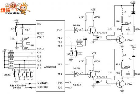
The steper motor driver system principle circuit is shown in the picture below.
The AT89C2051 outputs the control pulses from the P1's P1.4~P1.7 port, then these pulse signals are phase inverted by the 74LS14 to enter 9014, after its amplification these signals then control the photoelectric switch. After optical isolation, the pulse signals' voltage and current are amplified by the power tube TIP122 and then drive the stepper motor every phase windings. It would make the stepper motor have the corotation, reversion, acceleration, deceleration and stop movement with differential pulse signals. L1 shown in the picture is one phase winding of the stepper motor. The AT89C2051 is chosen to use 22MHz crystal. The purpose of using the high-frequency crystal is minimizing the influences on the PC pulse signal cycles by the AT89C2051 in mode 2.
The RL1~RL4 is winding resistance shown picture 1. The 50Ω resistance is a external resistance for current limiting, which is also a component to improve the loop circuit's time constant. D1~D4 are freewheeling diodes, which making the opposing electromotive force produced by motor winding be attenuated through them to protect the power tube TIP122 from damaged.
If the 50Ω external resistance is in parallel with a 200uF capacitor, it would improve the front of the current pulses which are transmitted to the stepper motor to improve the high-frequency performance of the stepper motor.
(View)
View full Circuit Diagram | Comments | Reading(1567)
CD4013 feather-touch time delay switch circuit
Published:2011/5/10 1:52:00 Author:chopper | Keyword: feather-touch, time delay switch
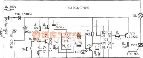
View full Circuit Diagram | Comments | Reading(2084)
Stepper Motor Working Timing Waveform Diagram
Published:2011/5/4 10:02:00 Author:Robert | Keyword: Stepper Motor, Working, Timing Waveform
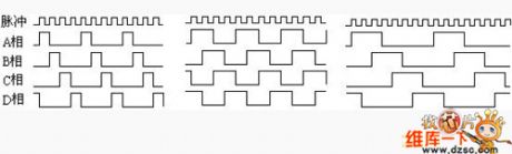
Stepper Motor Working Timing Waveform Diagram is shown below.
According tothe differences of the power turn-onorder of four-phase stepper motor, the working types could be divided into three types: singld four-beat, double four-beat and eight-beat. Single four-beat type's stepper angle is equal with the double four-beat, but single four-beat type's torque is little. Eight-beatworking type's stepper angle is half of the single and double four-beat type's. So, the eight-beat working type couldnot onlymaintain a high torque but also improve the control accuracy.
The single four-beat, double four-beat and eight-beat working type's power turn-on timing waveform diagrams are shown in the picture 2.a, b, c separately.
(View)
View full Circuit Diagram | Comments | Reading(2412)
Squirrel Cage Motor Pole Changing And Speed Governing Wiring Circuit
Published:2011/4/26 5:14:00 Author:Robert | Keyword: Squirrel Cage, Motor, Pole Changing, Speed Governing, Wiring
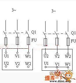
Squirrel Cage Motor Pole Changing And Speed Governing Wiring Circuit is shown above. (View)
View full Circuit Diagram | Comments | Reading(1364)
Squirrel Cage Autotransformer Motor Starter Circuit
Published:2011/4/23 3:02:00 Author:Robert | Keyword: Squirrel Cage, Autotransformer, Motor Starter
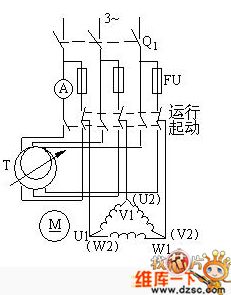
Squirrel Cage Autotransformer Motor Starter Circuit is shown above. (View)
View full Circuit Diagram | Comments | Reading(1444)
Squirrel Cage Motor Direct Starting Circuit
Published:2011/4/23 3:07:00 Author:Robert | Keyword: Squirrel Cage, Motor, Direct Starting
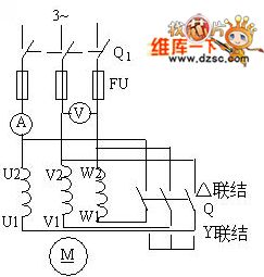
Squirrel Cage Motor Direct Starting Circuit is shown above. (View)
View full Circuit Diagram | Comments | Reading(847)
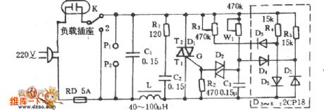
Electric Fan Sound Control Speed Governing Circuit
Published:2011/4/23 3:17:00 Author:Robert | Keyword: Electric Fan, Sound Control, Speed Governing
Electric Fan Sound Control Speed Governing Circuit is shown below:
(View)
View full Circuit Diagram | Comments | Reading(799)
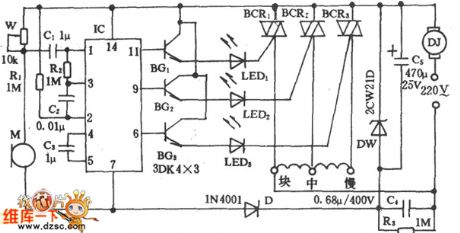
Electric Fan High-Power Speed Control Circuit
Published:2011/4/23 9:55:00 Author:Robert | Keyword: Electric Fan, High-Power, Speed Control
Electric Fan High-Power Speed Control Circuit is shown below:
(View)
View full Circuit Diagram | Comments | Reading(974)
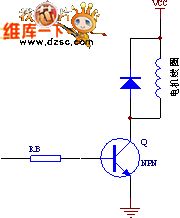
Typical Brushless DC Motor Wiring Circuit
Published:2011/4/23 1:21:00 Author:Robert | Keyword: Brushless DC Motor, Wiring
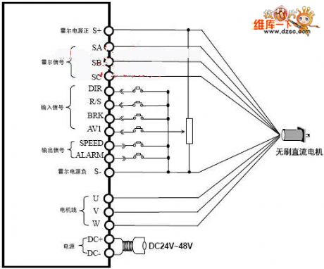
Typical Brushless DC Motor Wiring Circuit is shown above. (View)
View full Circuit Diagram | Comments | Reading(2092)
Suzuki Lift Circuit Schematic Diagram
Published:2011/4/22 23:55:00 Author:Robert | Keyword: Suzuki, Lift
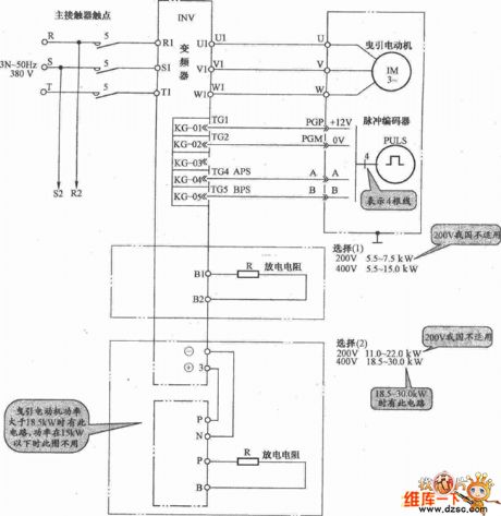
Suzuki Lift Circuit Schematic Diagram is shown below:
(View)
View full Circuit Diagram | Comments | Reading(1724)
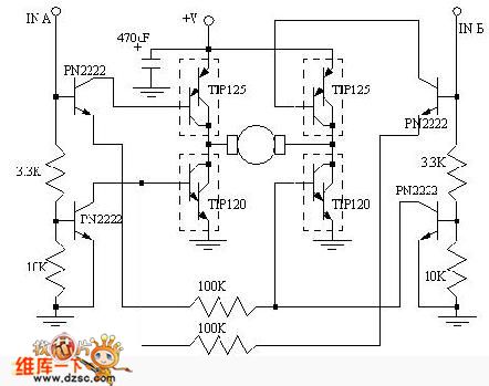
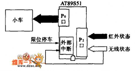
Main drive circuit diagram of micro-motor
Published:2011/4/1 3:33:00 Author:Nicole | Keyword: micro-motor, main drive
View full Circuit Diagram | Comments | Reading(720)
MCLR connection manual button switch circuit diagram
Published:2011/4/10 22:29:00 Author:muriel | Keyword: MCLR connection manual button switch
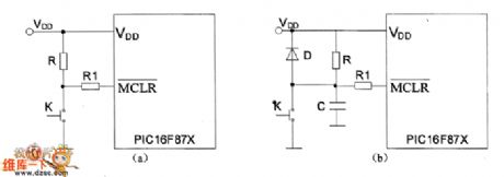
MCLR connection manual button switch circuit diagram as shown
(View)
View full Circuit Diagram | Comments | Reading(3858)
| Pages:5/6 123456 |
Circuit Categories
power supply circuit
Amplifier Circuit
Basic Circuit
LED and Light Circuit
Sensor Circuit
Signal Processing
Electrical Equipment Circuit
Control Circuit
Remote Control Circuit
A/D-D/A Converter Circuit
Audio Circuit
Measuring and Test Circuit
Communication Circuit
Computer-Related Circuit
555 Circuit
Automotive Circuit
Repairing Circuit