
Circuit Diagram
Index 1946
AP2426GEY、AP2428GEY Internal Circuit
Published:2011/5/6 0:43:00 Author:Felicity | Keyword: Internal Circuit,
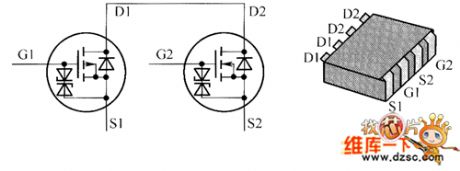
The picture above shows the AP2426GEY、AP2428GEY Internal Circuit. (View)
View full Circuit Diagram | Comments | Reading(417)
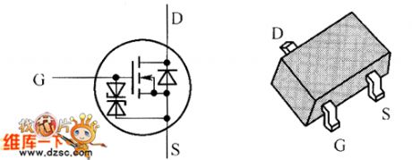
AP2315GEN Internal Circuit
Published:2011/5/6 0:45:00 Author:Felicity | Keyword: Internal Circuit,
The picture above shows the AP2315GEN internal circuit. (View)
View full Circuit Diagram | Comments | Reading(440)
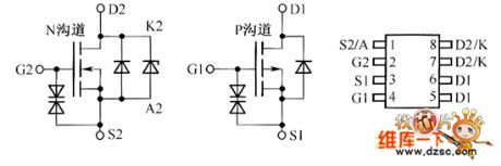
AP1332EU、AP1332GEU、AP2308GEN、AP2318GEN Internal Circuit
Published:2011/5/6 0:48:00 Author:Felicity | Keyword: Internal Circuit,
The picture above shows the AP1332EU、AP1332GEU、AP2308GEN、AP2318GEN internal circuit. (View)
View full Circuit Diagram | Comments | Reading(464)
AOP610 Internal Circuit
Published:2011/5/6 0:50:00 Author:Felicity | Keyword: Internal Circuit,
The picture above show the AOP610 internal circuit. (View)
View full Circuit Diagram | Comments | Reading(662)
Travel Charger(Ericsson 788) Circuit
Published:2011/5/6 0:36:00 Author:Sue | Keyword: Travel Charger, Ericsson 788
View full Circuit Diagram | Comments | Reading(734)
Wide Dynamic Range Gain Control Amplifier Circuit
Published:2011/5/5 23:56:00 Author:Joyce | Keyword: Wide, Dynamic Range, Gain, Control, Amplifier
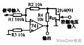
Wide Dynamic Range Gain Control Amplifier Circuit is shown in the graph below.Experience has proved that when using FET as variable resistor to control the amplifier's gain, if the input signal is 1% of the pinch-off voltage, there will be 1% distortion . And in the feedback circuit, if one uses two resistances and a field-effect tube to constitute a T network, the signals could be added to the field-effect tube after being reduced by R1, R2. Therefore it is able to control sizable signals. (View)
View full Circuit Diagram | Comments | Reading(536)
Isolating AC "weng" sound electro-optical isolating circuit
Published:2011/5/2 7:55:00 Author:Nicole | Keyword: AC, electro-optical isolating
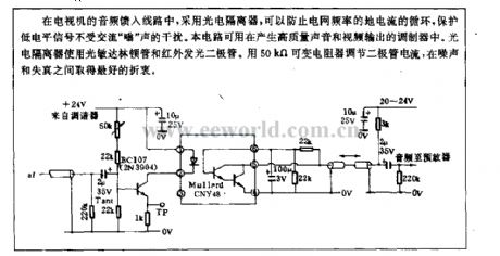
The TV audio feed-in circuit adopts photoelectric isolator to prevent grid frequency ground current from cycling, to protect low level singal from the interference of AC ong . This circuit is used in the modulator which can produce high quality sound and video output. The photoelectric isolator adopts photosensitive Darlington Transistor and infrared LED.It can use50kΩ variable resister to regulate diode current,then it will obtain best compromise between noise and distortion. (View)
View full Circuit Diagram | Comments | Reading(759)
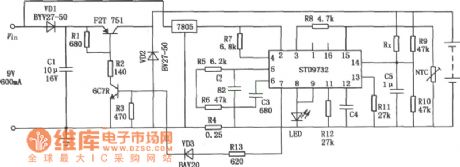
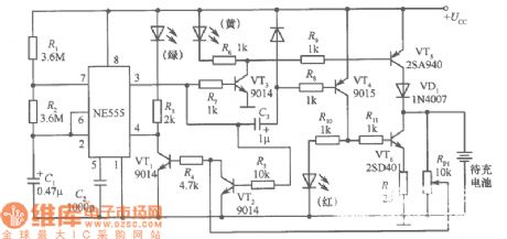
Simplified Charger Circuit Composed of STD 9732
Published:2011/5/6 0:43:00 Author:Sue | Keyword: Simplified, Charger
View full Circuit Diagram | Comments | Reading(579)
Gain Program-controlled Instrument Amplifier Circuit
Published:2011/5/6 0:04:00 Author:Joyce | Keyword: Gain, Program-controlled Instrument, Amplifier
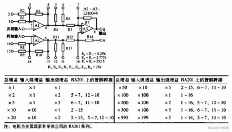
Gain Program-controlled Instrument Amplifier Circuit is shown in the graph below.The circuit uses LH0044 operational amplifer.Connecting it according to the table, one can get different gains (1 ~ 995). Offset voltage has been set below 25μV ,and thetypical bias current is 10μA.
(View)
View full Circuit Diagram | Comments | Reading(656)
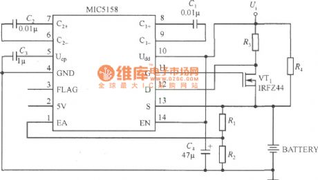
Battery Charger Circuit Composed of MIC5158
Published:2011/5/6 0:41:00 Author:Sue | Keyword: Battery Charger
View full Circuit Diagram | Comments | Reading(651)
Charger(Walkman)Circuit
Published:2011/5/6 0:33:00 Author:Sue | Keyword: Charger, Walkman,
View full Circuit Diagram | Comments | Reading(1111)
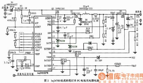
Benq Laptop Battery Charger Circuit
Published:2011/5/6 0:29:00 Author:Sue | Keyword: Benq, Laptop, Battery, Charger
View full Circuit Diagram | Comments | Reading(2746)
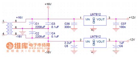
Dual Stabilized Voltage Output Circuit
Published:2011/5/6 0:32:00 Author:Sue | Keyword: Dual, Stabilized Voltage, Output
View full Circuit Diagram | Comments | Reading(671)
Gain Adjustable Test Equipment Isolation Amplifier Circuit
Published:2011/5/6 0:14:00 Author:Joyce | Keyword: Gain, Adjustable, Test Equipment, Isolation Amplifier

Gain Adjustable Test Equipment Isolation Amplifier Circuit is shown in the graph below.With optical coupling isolation amplifier ISO100, one can form a gain test equipment isolation amplifier.The gain of the circuit ranges from 10 to 1000 . The input signal needs to be negative value. The input and output stage of ISO100 is supplied by two groups of ± 15V power supply respectively.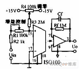 (View)
View full Circuit Diagram | Comments | Reading(704)
Drive display circuit with multi-channel turn mending method
Published:2011/4/19 7:08:00 Author:Nicole | Keyword: multi-channel, turn mending method, drive display
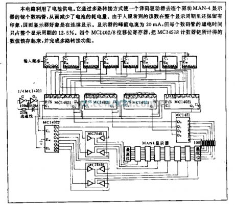
This circuit uses battery powered. It makes an encode driver to drive LEDs of MAN-4 display one by one through multi-channel transit way, then to reduce the power consumption of battery. Because the reading which people seen is still have impression in whole display cycle, so the display seem to display continuously. The peak current of display is 20mA, the test duration of each LED only accounts for 12.5% of the whole display cycle. Four MC1402/8 FCSR, to latch the value which is form MC14518 count chain,then itaccomplishes the multi-channel transit function. (View)
View full Circuit Diagram | Comments | Reading(656)
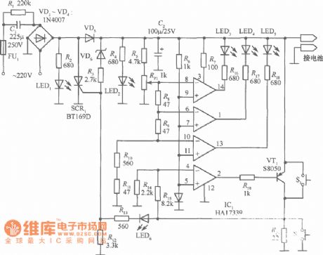
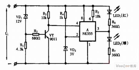
Camera Photometric System Circuit
Published:2011/5/6 0:28:00 Author:Joyce | Keyword: Camera Photometric System Circuit
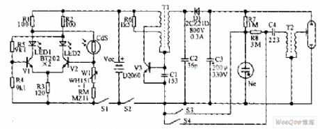
The camera photometric system is composed of two transistors. When the luminance of the subject to be shot is weak, the value of the cadmium sulphide photoconductive resistance will increase,then LED2 will not flash due to cutoff of V2. At this time V1 will breakover,and LED1 will shine. When the luminance of the subject to be shot increases, the resistance of CdS will decrease, and then LED2 will go out,and LED2 will give out light. In this way, it points out whether the flashlight is being used or not.
(View)
View full Circuit Diagram | Comments | Reading(551)
Integrated regulated power supply with overvoltage protection composed of CW137
Published:2011/5/5 8:11:00 Author:Nicole | Keyword: regulated power supply, overvoltage protection
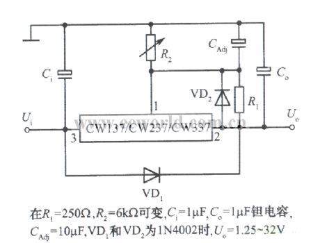
Integrated regulated power supply with overvoltage protection composed of three terminal adjustable negative output voltage integrated regulator CW137.
When R1=250Ω, R2=6Ω, it is changeable, Ci=1μF, Co=1μF Ta capacitor, CAdj=10μF, VD1 and VD2 are 1N4002, Uo=1.25~32V. (View)
View full Circuit Diagram | Comments | Reading(575)
Using NE555 Skillfully as DC Voltage Monitor Circuit
Published:2011/5/5 2:54:00 Author:Joyce | Keyword: Using NE555 Skillfully, as DC Voltage, Monitor
Using NE555 Skillfully as DC Voltage Monitor Circuit (View)
View full Circuit Diagram | Comments | Reading(1733)
Differentiation exposure meter circuit
Published:2011/4/29 4:54:00 Author:Nicole | Keyword: exposure meter
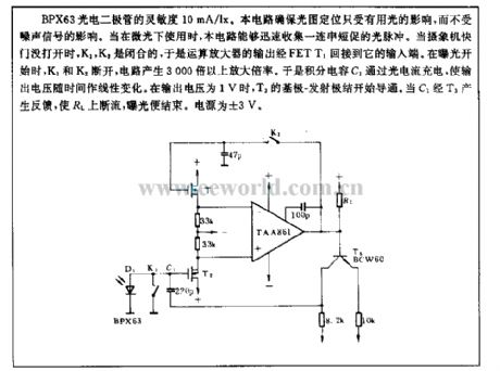
The sensitivity of BPX63 photodiode is 10mA/lx. This circuit can ensure the light and figure location only influenced by the useful light, and it will not beinfluenced by the noise singal. When it is used under gleam, this circuit can fast collect a series of short optical pulse. When the camera shutter is not opened, K1, K2 are closed, the operational amplifier output is connected to its inout terminal by FETT1. when it starts to expose, k1, K2 turn off, the circuit produce more than 3000 times enlargement ratio. Integral capacity C1 is charged by photocurrent, it makes the output voltage linear change with time. When the output voltage is 1V, T3's base-emitter junction starts to turn on. When C1 produces feedback by T3, RL is discontinuous flow, the exposure is ended. The power supply is ±3V. (View)
View full Circuit Diagram | Comments | Reading(706)
Using NE555 Skillfully as Linear Capacitance Tester Circuit
Published:2011/5/5 2:54:00 Author:Joyce | Keyword: Using NE555 Skillfully as, Linear, Capacitance, Tester
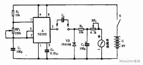
Using NE555 Skillfully as Linear Capacitance Tester Circuit (View)
View full Circuit Diagram | Comments | Reading(3773)
| Pages:1946/2234 At 2019411942194319441945194619471948194919501951195219531954195519561957195819591960Under 20 |
Circuit Categories
power supply circuit
Amplifier Circuit
Basic Circuit
LED and Light Circuit
Sensor Circuit
Signal Processing
Electrical Equipment Circuit
Control Circuit
Remote Control Circuit
A/D-D/A Converter Circuit
Audio Circuit
Measuring and Test Circuit
Communication Circuit
Computer-Related Circuit
555 Circuit
Automotive Circuit
Repairing Circuit