
Circuit Diagram
Index 1961
Shape and internal wiring circuit diagram of Beijing Cherokee starter relay
Published:2011/5/4 3:02:00 Author:Rebekka | Keyword: Beijing Cherokee , starter relay
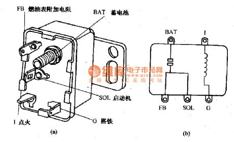
Shape and internal wiring circuit diagram of Beijing Cherokee starter relay. (View)
View full Circuit Diagram | Comments | Reading(1707)
LED Open-circuit Protective Circuit
Published:2011/5/3 8:34:00 Author:Joyce | Keyword: LED, Open-circuit, Protective, CP2126
As you can see,italmost has no impact on the receiving sensitivity of mobile phones that whether CP2126 works or not .But if the chip X is at work,the receiving sensitivity would decrease because of the interference caused by EMI . Meanwhile, under the typical condition that CP2126 with a voltage input of 3.6 V drives three white light LED, the conversion efficiency can reach 83% .
The design of PCB will also have a great influence on the performance of the circuit. Generally, routings on the part of high frequency should be as short and thick as possible,vias to the ground should be as lagre and abundant aspossible to meet the requirements claimed in the relevant information of CP2126 .
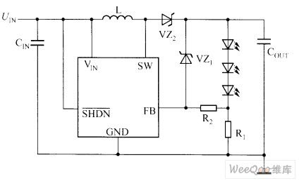
In application, LED may happen to have some open fault.In this case, because the feedback voltage of pin CS will keep at 0, so if there is no protective circuit, this kind of boost circuit will boost till the switching tube within gets punctured and breaks down.Therefore, chips without the protection of built-in protective circuit need to add a Zener diode to protect the internal switching tube. The LED open-circuit protection circuit is shown in the graph.It is obvious that such protective circuit will increase the cost of the system and the acreage of PCB . Another method to protect the circuit is to add a pin, use capsulation like SOT23-6L,and sample and detect the voltage of UOUT. Because CP2126 has a built-in output open-circuit protective circuit, it can ensure that the chip would not be damaged in the circumstance that no change has to be done to the peripheral application circuit and LED is open.When malfunction is removed, thechipcan again work properly. (View)
View full Circuit Diagram | Comments | Reading(815)
880MHz Low Noise Amplification Application Circuit Composed Of RF2347
Published:2011/5/3 20:00:00 Author:Robert | Keyword: 880MHz, Low Noise, Amplification, Application
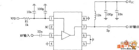
This pictureshown below is the 880MHz low noise amplification application circuit composed of RF2347. The RF signal is inputed to the 3 foot, and is outputed from 7 foot after amplification in the amplifiers. The 3 footis directly coupled with the internal amplifier, so a 22pF block-DC coupling capacitor is added outside the 3 foot, and therelated resistance would be 50Ω when working at 836MHz. The 7 foot is the output port of the open collector electrode, which can be connected to power Vcc through choke coil or matching inductor. This foot's typical matching resistance is 50Ω, and can be connected to external output-matching networks to suit the amplifier's output resistance, so that can get the maximum output power and efficiency. The 1 foot is for power down control terminal, which is used to control the drift current. When VPD=(2.8±0.1)V (Typical IPD is 8.5mA) the circuit begins to work; when VPD<0.9V the circuit becomes closed; VPD reqiures external RF bypass circuit.
(View)
View full Circuit Diagram | Comments | Reading(582)
Input status indication circuit
Published:2011/5/3 6:53:00 Author:Christina | Keyword: Input status, indication
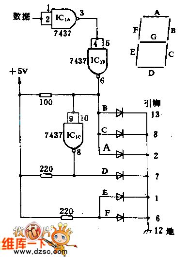
This circuit monitors the bit data input, and shows H or L on the 7-segment digital display by the conditions. This circuit uses two 7437 inverters and one DL-704 LED common cathode. The diode symbol means one segment of the digital tube (when segment A displaying H or L , the diode symbol means nothing). The 7437 inverter's power connection are: (14) connects to +5V, (7) connects to ground.
(View)
View full Circuit Diagram | Comments | Reading(668)
Beijing Cherokee light off-road vehicle air-conditioning control wiring circuit diagram
Published:2011/5/4 2:51:00 Author:Rebekka | Keyword: Beijing Cherokee, light off-road vehicles
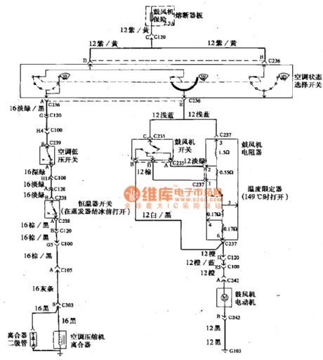
Beijing Cherokee light off-road vehicle air-conditioning control wiring circuit diagram. (View)
View full Circuit Diagram | Comments | Reading(934)
Beijing Cherokee light off-road vehicles instrument panel lighting wiring circuit diagram
Published:2011/5/4 2:49:00 Author:Rebekka | Keyword: Beijing Cherokee, light off-road vehicles
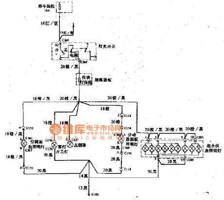
Beijing Cherokee light off-road vehicles instrument panel lighting wiring circuit diagram. (View)
View full Circuit Diagram | Comments | Reading(722)
Accord sedan automatic temperature control system circuit diagram
Published:2011/5/4 2:08:00 Author:Rebekka | Keyword: Accord sedan, temperature control system
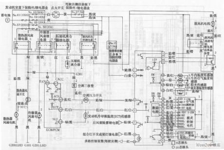
Accord sedan automatic temperature control system circuit diagram. (View)
View full Circuit Diagram | Comments | Reading(1114)
Beijing Cherokee light off-road vehicles audio and dome light wiring circuit diagram
Published:2011/5/4 2:50:00 Author:Rebekka | Keyword: Beijing Cherokee , light off-road vehicles, audio and dome light wiring
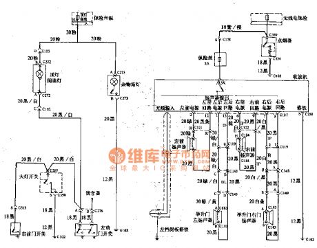
Beijing Cherokee light off-road vehicles audio and dome light wiring circuit diagram. (View)
View full Circuit Diagram | Comments | Reading(586)
Santana 2000(gasoline injection motor)car air conditioner(continuation)circuit wiring circuit diagram(2)
Published:2011/5/4 2:31:00 Author:Nicole | Keyword: Santana 2000, gasoline injection motor, car air conditioner

123-microswitch; 124-thermostat; 128-air conditioner(H, V, A, C)control switch; 129-warm wind speed range switch(four gears); 130-ventilation system air conditioner resistance; 131-air conditioner warm wind blower; 132-air conditioner relay. (View)
View full Circuit Diagram | Comments | Reading(1760)
Santana 2000(gasoline injection motor)car air conditioner(continuation)circuit wiring circuit diagram(1)
Published:2011/5/4 2:21:00 Author:Nicole | Keyword: Santana 2000, gasoline injection motor, car air conditioner
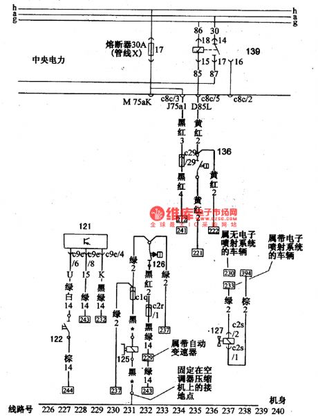
121-overload relay; 122-overload relay switch; 125-air conditioner compressor electromagnetism clutch; 126-low voltage switch bar; 127-electromagnetic valve of idle speed corrector; 36-high voltage regulator; 139-cooling system relay. (View)
View full Circuit Diagram | Comments | Reading(1713)
Practical two-color LED circuit diagram
Published:2011/5/4 2:46:00 Author:Rebekka | Keyword: Practical two-color LED
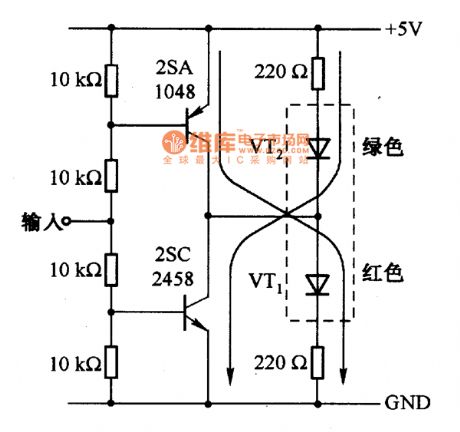
The actual circuit of using two-color LED display is shown as above. When input +5 V, VT1 turns on, green LED light; Input is 0, VT2 turns on, red LED light. (View)
View full Circuit Diagram | Comments | Reading(1024)
Measuring small current amplifier circuit diagram
Published:2011/5/4 1:40:00 Author:Rebekka | Keyword: Measuring small current amplifier
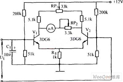
Measuring small current amplifier circuit diagram. (View)
View full Circuit Diagram | Comments | Reading(597)
Photocoupler AC switches circuit diagram
Published:2011/5/4 2:01:00 Author:Rebekka | Keyword: Photocoupler AC switches
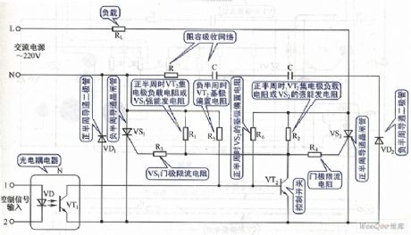
Photocoupler AC switches circuit diagram. (View)
View full Circuit Diagram | Comments | Reading(708)
Dynamic fit light control AC switches circuit diagram
Published:2011/5/4 1:59:00 Author:Rebekka | Keyword: Dynamic fit light control, AC switches

Dynamic fit light control AC switches circuit diagram. (View)
View full Circuit Diagram | Comments | Reading(838)
Both-way thyristor motor control circuit diagram 1
Published:2011/5/4 1:42:00 Author:Rebekka | Keyword: Both-way thyristor motor control
Both-way thyristor motor control circuit diagram. (View)
View full Circuit Diagram | Comments | Reading(785)
Both-way thyristor motor control circuit diagram 2
Published:2011/5/4 1:48:00 Author:Rebekka | Keyword: Both-way thyristor motor control
Both-way thyristor motor control circuit diagram.
(View)
View full Circuit Diagram | Comments | Reading(1461)
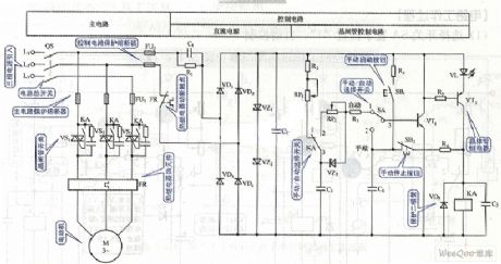
TDA4605 thick film switching power supply IC diagram
Published:2011/5/4 2:11:00 Author:Ecco | Keyword: thick film, switching power supply, IC
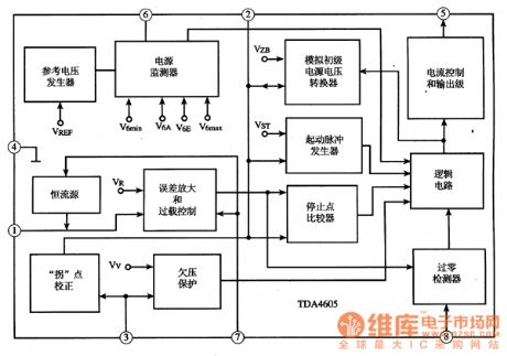
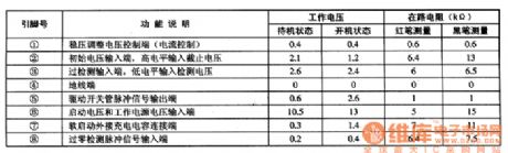
TDA4605 thick film switching power supply IC diagram is produced by Philips, which is widely used in domestic and imported large screen color TV and color display. TDA4605 integrated circuit includes voltage regulator sampling processing circuit, under voltage protection detection circuit, the excitation pulse output circuit, soft start control circuit, its internal circuit diagram shown in Figure 1 million. The 8-pin IC-style packaging million, the pin functions and data listed in Table 1. Figure 1 TDA4605 integrated circuit within the circuit block diagram
Table 1 showsTDA4605 integrated circuit pin functions and data
(View)
View full Circuit Diagram | Comments | Reading(1295)
Tape recorder remote control display circuit
Published:2011/4/29 4:52:00 Author:Nicole | Keyword: tape recorder, remote control
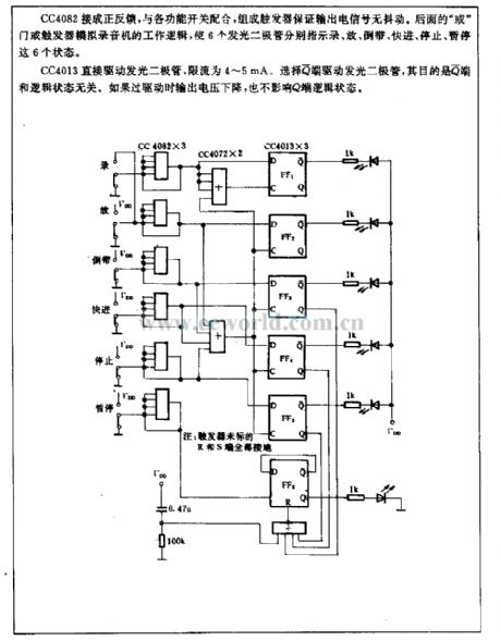
CC4082 is connected into positive feedback, it is coordinated with all kinds function switches, they form a trigger to ensure the output electrical signal against chattering. The later or gate or trigger simulates the work logic of tape recorder, the six LEDs indicate the six states of recording, putting, rewinding, fast marching, stopping, time-out.
CC4013 drives LED directly, the limited current is 4~5mA. To choose Q terminal to drive LED, because the Q terminal is unrelated to logic state. If the output voltage drops, it has no influence on Q terminal logic state. (View)
View full Circuit Diagram | Comments | Reading(726)
Improved photoelectric isolator linear circuit
Published:2011/4/29 4:50:00 Author:Nicole | Keyword: photoelectric isolator
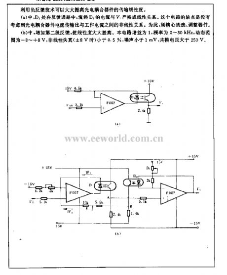
Using negative feedback technology can improve the transport linearity of photoelectric isolator device.
In figure (a), when D1 is in the feedback path, its current is linear with V1. The shortage of this circuit is not considering the nonlinear relationship between photoelectric isolator device current current transfer ratio and working current. So we should choose and adjust devicecarefully.
In figure (b), increasing secondary feedback can improve the linearity. The circuit gain is 1, the frequency is 0~30kHz, the dynamic range is -8~+8V, the nonlinear distortion(it is ±8V)is lower than 0.5%, the noise is lower than 1mV, the common-mode voltage is higher than 250V. (View)
View full Circuit Diagram | Comments | Reading(543)
Industrial and mining field indicator light circuit
Published:2011/5/2 7:51:00 Author:Nicole | Keyword: industrial and mining field, indicator light
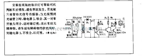
The indicator lights are fixed in the field that can help driver tojudge the situation behind car, to prevent accidents. Using phototransistor as singal sensor, when the light fell on photosensitive tube, relay J0 pulls in, a pair of often opening contacts are closed, then the green light is on, it means that there is no obstruction behind car. If there is obstruction to keep out light, then relay J0 dose not pull in, the red lights on. (View)
View full Circuit Diagram | Comments | Reading(723)
| Pages:1961/2234 At 2019611962196319641965196619671968196919701971197219731974197519761977197819791980Under 20 |
Circuit Categories
power supply circuit
Amplifier Circuit
Basic Circuit
LED and Light Circuit
Sensor Circuit
Signal Processing
Electrical Equipment Circuit
Control Circuit
Remote Control Circuit
A/D-D/A Converter Circuit
Audio Circuit
Measuring and Test Circuit
Communication Circuit
Computer-Related Circuit
555 Circuit
Automotive Circuit
Repairing Circuit