
Circuit Diagram
Index 1968
Three-phase step wave inverter output transformer winding connection type and output voltage waveform
Published:2011/4/14 1:33:00 Author:muriel | Keyword: Three-phase, step wave inverter, output transformer, winding connection type , output voltage waveform
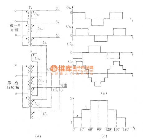
As shown in the figure: (a) is Three-phase step wave inverter output transformer winding connection type .(b) is output voltage waveform. (View)
View full Circuit Diagram | Comments | Reading(3896)
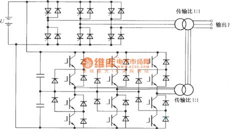
Three phase bridge type inverter circuit diagram
Published:2011/4/14 1:33:00 Author:muriel | Keyword: Three phase, bridge type , inverter circuit diagram
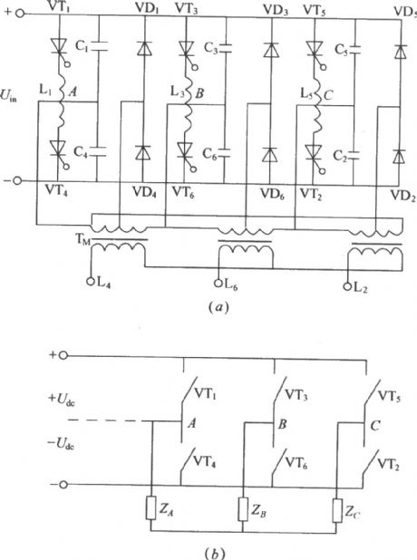
As shown in the figure is the traditional three-phase bridge type inverter circuit:VT1~VT6 is thyristor, L1~L6 is commutation reactor, C1~C6 is commutating capacitor, the thyristor shut-off circuitconsists of the two parts. VD1~VD6 is feedback diode. According to the work principle of the thyristor, it based on the 3-phaseAC inputpower supply , If the thyristor bearthe maximumpositive anode voltage and the control gate gets trigger pulse, it will switch to conducting state. On the contrary the thyristor under the conducting state with the enough inverse anode voltage will switch to cut off state. The figure(b) is the simplified figure of figure(a). (View)
View full Circuit Diagram | Comments | Reading(2941)
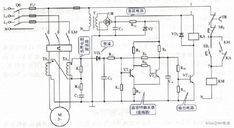
Siganl station power supply distribution system diagram
Published:2011/4/14 2:26:00 Author:muriel | Keyword: Siganl station , power supply, distribution , system diagram
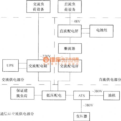
Communication power is the power which isdirectlysupplying to the communication equipment. Communication power isthe key part and subject of the signal station , signal station power supply also includes theguarantee building load of the short time interrupt, such as CRAC etc. General signal station power supply component isas shown. (View)
View full Circuit Diagram | Comments | Reading(721)
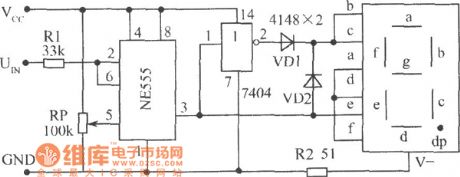
The level test circuit diagram composed of NE555 single time base circuit
Published:2011/5/3 4:07:00 Author:Ecco | Keyword: level test , single , time base circuit
View full Circuit Diagram | Comments | Reading(734)
Topological structure of Combined type hybrid multilevel translation circuit
Published:2011/4/14 1:49:00 Author:muriel | Keyword: Combined type , hybrid multilevel translation circuit
View full Circuit Diagram | Comments | Reading(474)
100v/1A Regulated voltage circuit
Published:2011/4/14 21:53:00 Author:muriel | Keyword: 100V/1A, Regulated voltage circuit
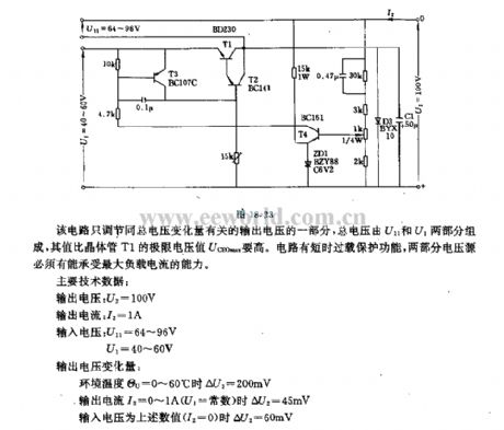
The circuit only adjusted the part of the output voltagewhich is about the voltage change of total voltage, the total voltage consists of U11 and U1 two parts, the limit voltage value of the transistor are higher than the Uceomax. The circuit has the short overload protection function, two parts of voltage source must have the capability to withstand the maximum load current.
Main technical data:
output voltage:U2=100V
output current:I2=1A
Input voltage: U11=64V to 96V, U1=40V to 60V
Output voltage variation:
When environment temperatureθU=0°C to 60°C, ΔU2=200mV
When output current I2=0A to 1A(U1=constant), ΔU2=45mV
When input current are the above values(I2=0), ΔU2=60mV (View)
View full Circuit Diagram | Comments | Reading(1119)
Negative sequence voltage-phase protection circuit diagram 2
Published:2011/5/3 3:10:00 Author:Rebekka | Keyword: Negative sequence, voltage-phase protection
Negative sequence voltage-phase protection circuit diagram (View)
View full Circuit Diagram | Comments | Reading(1401)
GM Wuling automobile united electronic electric control system circuit diagram
Published:2011/5/3 3:14:00 Author:Rebekka | Keyword: GM Wuling automobile , electric control system
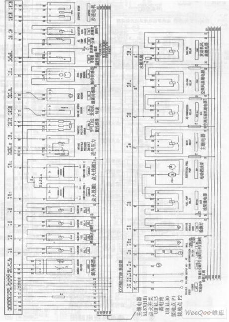
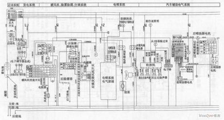
GM Wuling automobile united electronic electric control system circuit diagram. (View)
View full Circuit Diagram | Comments | Reading(1416)
The level test circuit diagram
Published:2011/5/3 3:57:00 Author:Ecco | Keyword: level , test
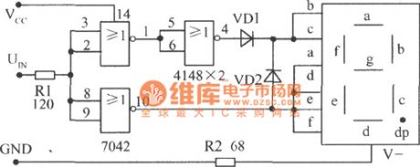
TTL NOR gate is connected as inverter, and it is equipped with common cathode LED,the high level shows q, low level displays 0. The circuit is shown in Fig.
(View)
View full Circuit Diagram | Comments | Reading(728)
GM Wuling automobile vehicle electrical system circuit diagram 1
Published:2011/5/3 3:12:00 Author:Rebekka | Keyword: GM Wuling Automobile, electrical system
GM Wuling automobile vehicle electrical system circuit diagram. (View)
View full Circuit Diagram | Comments | Reading(2789)
Bridge sensor signal amplifier AD22055 typical application circuit diagram
Published:2011/5/3 3:17:00 Author:Rebekka | Keyword: Bridge sensor signal amplifier, typical application circuit
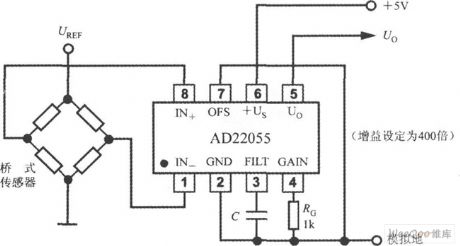
Bridge sensor signal amplifier AD22055 typical application circuit diagram. (View)
View full Circuit Diagram | Comments | Reading(919)
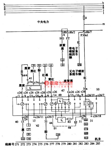
Santana 2000(fuel injection motor)car radio automatical antenna circuit wiring circuit diagram
Published:2011/5/3 3:08:00 Author:Nicole | Keyword: Santana 2000, fuel injection motor, car radio, antenna
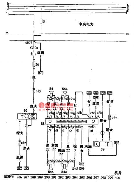
54-port forward loudspeaker; 54a-starboard forward loudspeaker; 54b-left rear loudspeaker; 54c-right rear loudspeaker; 58-radio; 59-electronic antenna; 60-electronic control antenna (View)
View full Circuit Diagram | Comments | Reading(1030)
Santana 2000(fuel injection motor)car combination appliance circuit wiring circuit diagram(2)
Published:2011/5/3 3:31:00 Author:Nicole | Keyword: Santana 2000, fuel injection motor, car combination appliance
40-vehicle speed odometer; 41-vehicle speed sensor; 42-motor tachometer; 43-resistor; 44-thermometer; 46-instrument regulator; 47-fuel gauge; 49-water temperature, fuel oil singal amplifier; 51-coolant alarm light; 52-fuel oil alarm light; 53-digital display clock (View)
View full Circuit Diagram | Comments | Reading(1796)
TA31033P call integrated circuit diagram
Published:2011/5/3 3:48:00 Author:Ecco | Keyword: call, integrated circuit
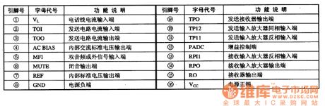
TA31033P is a call-specific integrated circuit, which is widely used in the call circuit of communications equipment, such as cordless phones and so on. 1. Pin function TA31033P uses 16-pin integrated circuit dual in-line inverse the package structure, the pin function is shown in Table 1. Table 1 shows TA31033P IC pin function.
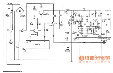
2. A typical application circuit The typical application circuit of calling circuit composed of TA31033P integrated circuit is shown in Figure 1.Figure 1 shows the typical application circuit of TA31033P integrated circuit.
(View)
View full Circuit Diagram | Comments | Reading(1674)
Decimal counting display shape circuit diagram
Published:2011/5/3 3:35:00 Author:Ecco | Keyword: Decimal, counting display , shape
Decimal counting display has the functions of BCD code information output, controlling off and invalid zero out, decimal point display, reset and carry functions, and has low power consumption, high reliability and long life. It is used in the digital equipment, instruments and various digital display electronic devices for the decimal counting. The shape is shown as Figure.
Decimal counting display shape is shown as the chart. (View)
View full Circuit Diagram | Comments | Reading(925)
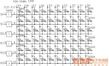
Digital Ganzhi and zodiac computative device circuit diagram
Published:2011/5/3 3:27:00 Author:Ecco | Keyword: Digital , Ganzhi , zodiac, computative device
View full Circuit Diagram | Comments | Reading(698)
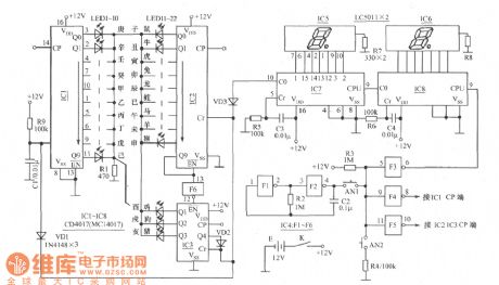
The timing responder circuit diagram
Published:2011/5/3 3:24:00 Author:Ecco | Keyword: timing responder
The circuit is shown as the circuit, the timing responder circuit is composed of the following parts: (1) clock pulse oscillation circuit. IC3 and its peripheral components form oscillator, period T = 1s. (2)display, light-emitting circuit (3) answer brake circuit (4) the end of the brake circuit when walking (5) resetting start (6) second frequency LED circuit:
(View)
View full Circuit Diagram | Comments | Reading(822)
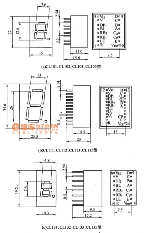
BSR (G) series of unit digital display outline and circuit diagram
Published:2011/5/3 3:31:00 Author:Ecco | Keyword: BSR (G) series , unit, digital display , outline
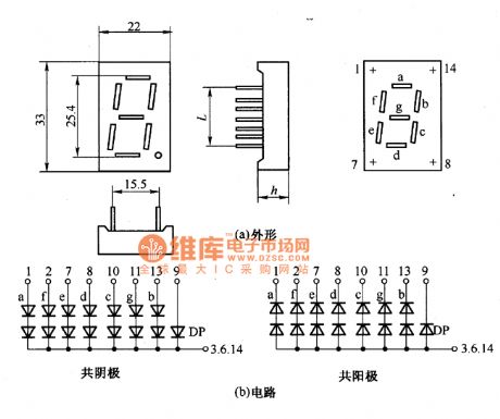
BSR (G) series of unit digital display outline and circuit diagram is shown as the chart. The main parameters are in Table.
BSR (G) series of unit digital display outline and circuit diagram is shown as the chart. (View)
View full Circuit Diagram | Comments | Reading(755)
TA31002 ringing integrated circuit diagram
Published:2011/5/3 3:41:00 Author:Ecco | Keyword: ringing, integrated circuit
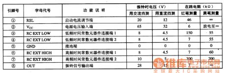
TA31002 is ringing integrated circuit produced by Toshiba, it is widely used in the communications equipment.
1. pin functions and data TA31002 IC uses 8-pin dual in-live-style package, the pin functions and data are listed in Table 1. Table 1 lists TA31002 IC pin functions and data.
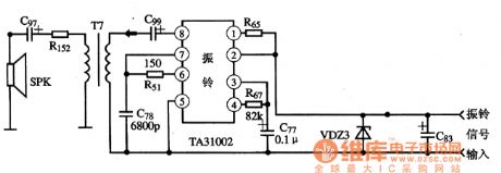
2. A typical application circuit The typical bell application circuitcomposed of TA31002 integrated circuit is shown in Figure 1. Figure 1 shows typical application circuit of TA31002 integrated circuit.
(View)
View full Circuit Diagram | Comments | Reading(1764)
Simple square wave generator circuit
Published:2011/3/17 23:10:00 Author: | Keyword: square wave generator
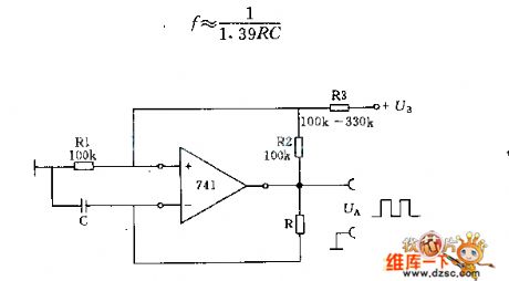
In the circuit parameter R1, R2 and R3 can adjust according to concrete condition, and osillator frequency decided to
(View)
View full Circuit Diagram | Comments | Reading(0)
| Pages:1968/2234 At 2019611962196319641965196619671968196919701971197219731974197519761977197819791980Under 20 |
Circuit Categories
power supply circuit
Amplifier Circuit
Basic Circuit
LED and Light Circuit
Sensor Circuit
Signal Processing
Electrical Equipment Circuit
Control Circuit
Remote Control Circuit
A/D-D/A Converter Circuit
Audio Circuit
Measuring and Test Circuit
Communication Circuit
Computer-Related Circuit
555 Circuit
Automotive Circuit
Repairing Circuit