
Circuit Diagram
Index 1976
Transistor time relay circuit diagram
Published:2011/4/29 5:10:00 Author:Rebekka | Keyword: Transistor time relay
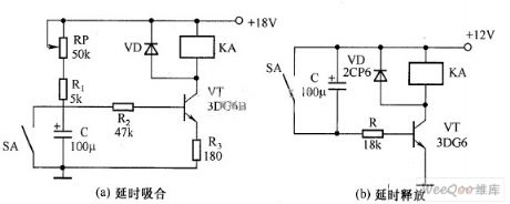
Transistor time relay circuit diagram. (View)
View full Circuit Diagram | Comments | Reading(1401)
Single-end forward converter circuit with RC and diode clamping circuit
Published:2011/4/21 21:37:00 Author:May | Keyword: Single-end, forward converter, RC and diode clamping
Single-ended forward converter has with removing magnetic winding and diode clamping circuit. Above which we talked about is the one with removing magnetic winding. The diagram shows single-end forward converter circuit with RC and diode clamping circuit. After VTl is cut off, winding N1 and VD3, R, C constitute a single-ended fly-back converter, the magnetizing current IM is attenuated by VD3, the reverse polarity voltage of N1 is superimposed on the input voltage U1 and applied between the emitters of VTl, that is Uce1 = Ui + Uc. Obviously, when U1 is greater than Uc, the cut-off time, toff will be less than on-time ton, that is the biggest turn-on pulse width can exceed half of the period. The conduction pulse width allows more, which can get a larger power output. The downside is that VTl will bear higher voltage, excitation energy will be consumed in resistor R. (View)
View full Circuit Diagram | Comments | Reading(592)
TOPSwitch--Ⅱ
Published:2011/4/21 21:08:00 Author:May
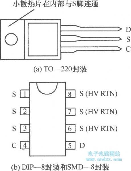
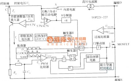
Pin arrangement of TOPSwitch --Ⅱ is shown in the diagram. It has three kinds of package. Among them, TO-220 package has heating panel and belongs to typical three-terminal device. Its shape is the same as 7800 series three-terminal linear regulators. DIP - 8 and SMD-8 package both has 8-pin package, but can be reduced to three; difference between the two is DIP-8 can be equipped with 8 pin IC socket, SMD-8 is surface patch and do not need to punch welding. Three pins of TOPSwitch - Ⅱ are control terminal C (Con-trol), source S (Source), drain D (Drain). TOPSwitch - Ⅱ internal block diagram is shown in below, it mainly includes 10 parts: (1) control voltage source; (2) band gap voltage reference; (3) oscillator; (4) shunt regulator / error amplifier; (5) pulse-width modulator; (6) gate driver stage and output stage; (7) over-current protection circuit; (8) Overheat protection and power-on reset circuit; (9) shutdown / auto-restart circuit; (10 ) high-voltage current source. In the diagram, Zc is control side of the dynamic impedance; RE is error voltage detection resistor; RA and CA make up low-pass filter with 7kHz cut off frequecny. The basic principle of TOPSwitch - Ⅱ is to use the feedback current Ic to adjust the duty cycle D, so as to achieve the purpose of regulation.
(View)
View full Circuit Diagram | Comments | Reading(682)
Nickel-cadmium battery charge protection circuit diagram
Published:2011/4/29 4:20:00 Author:Rebekka | Keyword: Nickel-cadmium battery, charge protection
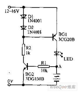
Nickel-cadmium rechargeable battery protection circuit is shown as below. The charging part is composed of D1, D2, R2 and BG1. The charge protection circuit is composed of BG2 and R1. When the nickel-cadmium batteries are charging, light emitting diode LED will be lighten. It indicates charging is normal. If the battery polarity is reversed, base BG2 will be negative potential, BG2 stops, BG1 the base potential will be raised, BG1 stops. It will not charge for nickel-cadmium battery, LED will not lit. It indicates the battery polarity is reversal. (View)
View full Circuit Diagram | Comments | Reading(2839)
Centigrade thermometre circuit
Published:2011/4/28 21:59:00 Author:Nicole | Keyword: centigrade thermometre
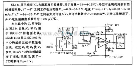
SL134 is three terminal type IC, it is used as temperature sensor. The measuring range is -55~+125℃, its exterior has two kinds: metal package and plastic package. The work voltage range of V+~V- is V±=0.9~30.0V, the current I+=Is+I-, Is=0.01~5.00mA, I+/I-=14~26, the maximum allowable value between R-V is 5V, the maximum allowable power consumption PD=200mW. Under the normal situation, the R-V voltage value temperature factor is about +227μV/K.
In this circuit, Ci is used to prevent SL134 self-excited, C2 and C3 are used to 5GOP-07 power supply decoupling, 5G1403 is as the core to form 5GM14433 three and a half digital display voltmeter. To change R3 or R6 then Vx will change in relation to the temperature with the proportion of 10mV/℃, to change Q1 can make Vx=0V when T=0℃. (View)
View full Circuit Diagram | Comments | Reading(731)
Lithium ion battery charging circuit diagram
Published:2011/4/29 4:03:00 Author:Rebekka | Keyword: Lithium ion battery charging
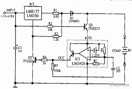
Lithium-ion battery charging circuit is shown as above. When it starts to charge. The battery voltage is below 8.4V, IC1's output has no output. Q2 off, LM317 work in the constant current output. When the battery voltage is increased to 8.4V, Q2 turns on, Q2 controls ADJ-side, so that the output voltage of IC2 significant declines and make the charge current maintain a very small value and the pool in a floating state. (View)
View full Circuit Diagram | Comments | Reading(7256)
Buick Century car HVAC system circuit diagram(8)
Published:2011/4/29 4:03:00 Author:Nicole | Keyword: Buick Century, car, HVAO system
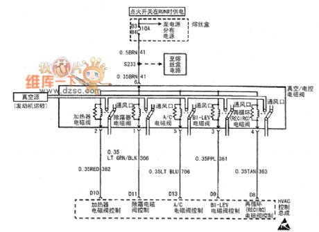
HVAO conreol assembly, vacuum solenoid valve, former LH and later temperature actuator(CJ4). (View)
View full Circuit Diagram | Comments | Reading(1085)
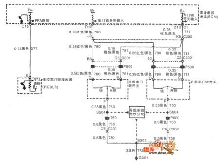
Shanghai GM Buick commercial vehicle(GL8) remote control latch circuit diagram(3)
Published:2011/4/29 4:09:00 Author:Nicole | Keyword: Shanghai GM Buick, commercial vehicle, remote control latch
View full Circuit Diagram | Comments | Reading(529)
Shanghai GM Buick commercial vehicle(GL8) remote control latch circuit diagram(2)
Published:2011/4/29 4:10:00 Author:Nicole | Keyword: Shanghai GM Buick, commercial vehicle, remote control latch
View full Circuit Diagram | Comments | Reading(479)
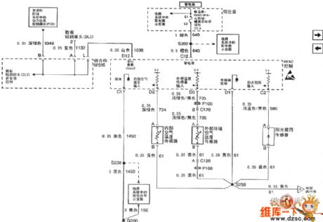
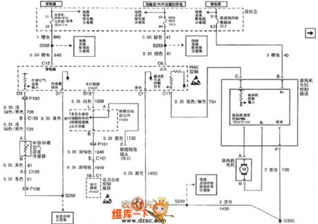
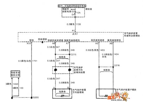
Buick Regal car air condition system GS3.0,GS+ circuit diagram(2)
Published:2011/4/29 4:13:00 Author:Nicole | Keyword: Buick Regal, car, air condition system
View full Circuit Diagram | Comments | Reading(617)
Buick Regal car air condition system GS3.0,GS+ circuit diagram(1)
Published:2011/4/29 4:12:00 Author:Nicole | Keyword: Buick Regal, car, air condition system
View full Circuit Diagram | Comments | Reading(713)
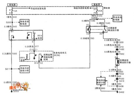
Shanghai GM Buick commercial vehicle(GL8) remote control latch circuit diagram(1)
Published:2011/4/29 4:09:00 Author:Nicole | Keyword: Shanghai GM Buick, commercial vehicle, remote control latch
View full Circuit Diagram | Comments | Reading(485)
Analog rocket emitting electronic game circuit diagram
Published:2011/4/29 4:04:00 Author:Ecco | Keyword: Analog , rocket emitting, electronic game
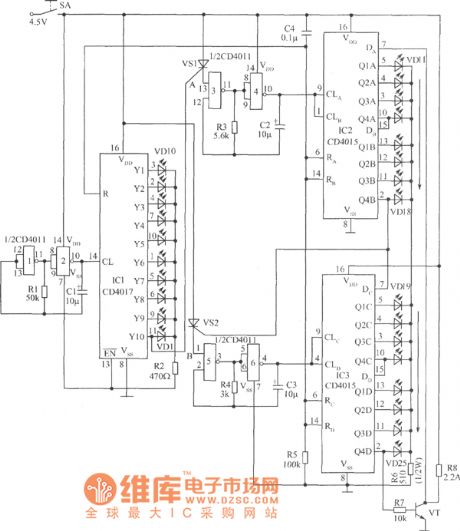
View full Circuit Diagram | Comments | Reading(1149)
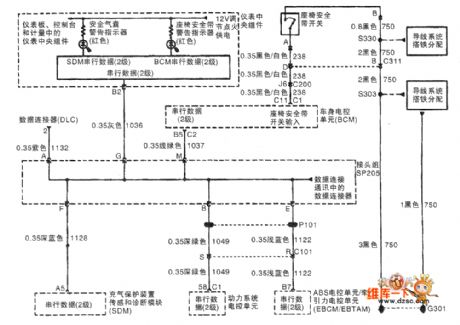
Shanghai GM Buick commercial vehicle(GL8) airbag circuit diagram(1)
Published:2011/4/29 4:07:00 Author:Nicole | Keyword: Shanghai GM Buick, commercial vehicle, airbag
View full Circuit Diagram | Comments | Reading(525)
Shanghai GM Buick commercial vehicle(GL8) airbag circuit diagram(2)
Published:2011/4/29 4:07:00 Author:Nicole | Keyword: Shanghai GM Buick, commercial vehicle, airbag
View full Circuit Diagram | Comments | Reading(511)
Battery fast charge circuit composed of BQ2002 battery fast charge control integrated circuit
Published:2011/4/27 9:16:00 Author:Nicole | Keyword: battery fast charge
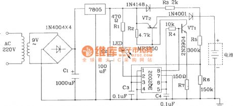
Transformer, diode and steady voltage IC7805 provide this circuit with +5V power voltage, the power voltage is divided by R5, R6 then transported to the BAT terminal of chip, it provides sample voltage. The resistance inputed from reststance partial pressure network to BAT terminal should not be lower than 200kΩ. When TM terminal is grounding, the fast charge rate is 1C, the fast charge supplementary time is 80min. (View)
View full Circuit Diagram | Comments | Reading(3379)
Using TL082 sine wave generator circuit diagram
Published:2011/4/29 0:48:00 Author:Rebekka | Keyword: sine wave generator
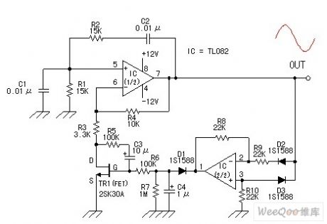
Using TL082 sine wave generator circuit diagramis shown as above. (View)
View full Circuit Diagram | Comments | Reading(4284)
± 15V and ± 26V output power supply circuit diagram
Published:2011/4/29 1:57:00 Author:Rebekka | Keyword: output power supply
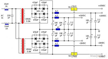
± 15V and ± 26V output power supply circuit diagram is shown as above. (View)
View full Circuit Diagram | Comments | Reading(602)
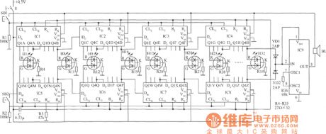
Advanced video game circuit diagram
Published:2011/4/29 4:02:00 Author:Ecco | Keyword: Advanced , video game
View full Circuit Diagram | Comments | Reading(1396)
Philips active subwoofer speaker power supply circuit diagram
Published:2011/4/29 1:59:00 Author:Rebekka | Keyword: Philips , active subwoofer speaker, power supply
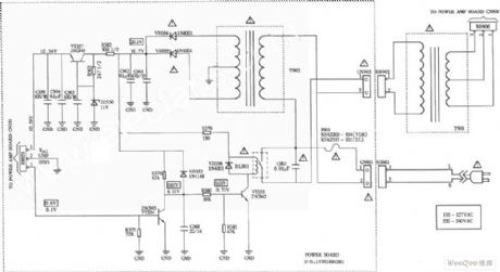
Philips active subwoofer speaker power supply circuit diagram is shown as above. (View)
View full Circuit Diagram | Comments | Reading(3283)
| Pages:1976/2234 At 2019611962196319641965196619671968196919701971197219731974197519761977197819791980Under 20 |
Circuit Categories
power supply circuit
Amplifier Circuit
Basic Circuit
LED and Light Circuit
Sensor Circuit
Signal Processing
Electrical Equipment Circuit
Control Circuit
Remote Control Circuit
A/D-D/A Converter Circuit
Audio Circuit
Measuring and Test Circuit
Communication Circuit
Computer-Related Circuit
555 Circuit
Automotive Circuit
Repairing Circuit